Essentials of Test-Bed Design: Compensating for Impact in Fighter-Jet Refueling
When the U.S. Navy developed in-flight-refueling equipment in the past, it used simple drop tests to study prototypes’ ability to withstand impacts. But the Navy wanted a better way to test fighter jets’ aerial refueling components, because old setups didn’t accurately simulate the impact between a jet’s probe and the refueling drogue.
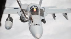
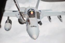
U.S. Navy fighter jets such as the F-18 can refuel in flight by extending a probe and “drinking” from a basketlike drogue on a tanker aircraft such as a KC-10. The operation is dangerous, and the equipment is subject to impact forces during engagement, not to mention the brutal environment of altitudes to 50,000 ft.
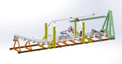
So Moog CSA Engineering in Mountain View, Calif., engineered a new test bed to more accurately simulate the forces. It has a probe mounted to a cart that rides on a track and an actively controlled suspension system that supports the drogue. Beneath the refueling probe assembly on the cart is a dynamometer that measures forces and moments on the probe's mast during impact.
Environmental conditions and the jet’s speed as well as the velocity of the drogue and fuel line were some of the calculations engineers factored into this groundbreaking design.
We asked CSA senior engineers Roland Smith and John Howat some questions about the new test bed, and here’s what they said.
What was wrong with the Navy’s prior system for testing aerial refueling components?
The prior system involved a simple drop test, where a drogue was dropped onto a surrogate-refueling probe. The height of release controlled the speed of impact. Unfortunately:
- This method produced nonrealistic results, as the Navy found failure modes that didn’t represent those seen in flight.
- There was no attempt to emulate aerodynamic loads on the drogue, which significantly affect the loads on the probe and airframe of the receiving aircraft — and likely a major cause of failure.
- The surrogate probe didn’t represent the probes used on actual aircraft (other than the tip that contained the latching interface to the drogue). Because the stiffness of the probe mast plays a large role in the magnitude of the impact loads, accurately representing the probe mast is important for recreating flight impacts.
- There was no way to measure the loads reacted into the probe, and it had less flexibility in the positioning of the probe and drogue prior to impact.
Why did the Navy work with Moog on this project?
Designers at the Navy’s NAVAIR had experience with us on a Small Business Innovate Research (SBIR) project developing load-relieving mechanisms for refueling probe masts. We were a subcontractor on the project to Stirling Dynamics, which specializes in aerodynamic and aeroelastic modeling. It simulated refueling-hose dynamics to help NAVAIR predict loads on the mast of the receiving aircraft during aerial refueling. We worked on the mechanical design and NAVAIR liked our work, so called us back when they decided to improve their probe-drogue tester.
What’s unique about the RPIT design?
The system consists of a probe mounted to a cart that rides on a track (similar to a roller coaster) and an actively controlled suspension system that supports the drogue. Beneath the cart’s refueling-probe assembly is a dynamometer that measures forces and moments on the probe mast during impact — in six degrees of freedom. Locks release the cart, which rides down an incline. (The height of the release on the incline controls cart speed at impact.) Then the cart carries the probe into the drogue (suspended over the track’s flat portion).
At impact, the drogue's actively controlled suspension system (which consists of three cables that span from the drogue through a pulley system and then are wrapped onto a motor-driven spool) regulates the tension in the suspension cables to recreate the aerodynamic loads and refueling-hose dynamics. As the cart passes the impact point, the motors feed out cable while maintaining the appropriate tension. This way, the impact dynamics can play out with the drogue attached to the probe as the cart moves further down the track.
The current RPIT configuration tests the probes from F/A-18 jet airplanes, but can accept probes from other platforms. The Navy hopes to test other drogue designs with the test bed.
What specific motion-control challenges did you overcome in designing and building the RPIT?
The impact between the probe and drogue is a fast event that requires precise timing between when the motors begin moving and the probe impacts the drogue. If not done correctly, the inertia of the motors’ rotating components is seen by the probe and corrupts the accuracy of the test. We saw this would be a problem, so we built a subscale test system that let us develop the controller and suspension mechanism before finalizing the RPIT. The subscale test bed had just one motor and cable assembly (as opposed to three on the full system) and recreated the impact on a smaller scale by dropping a mass onto a target supported by the cable. Thanks to this system, we devised better controls and a pulley mechanism that minimizes the effect of motor inertias on results.
Controlling dynamic tension in a cable is also challenging. A cable under tension exhibits lots of vibration modes (like a guitar string), and these dynamics are a function of cable tension and the length of cable. Controls for regulating the simulated aerodynamic drag loads had to withstand varying parasitic dynamics. So, we developed algorithms using a subscale test bed — as well as model-based design — to identify problems related to this dynamics-and-control challenge early.
We engineered the mechanical design in SolidWorks, then performed finite-element stress analysis in SolidWorks Simulation and NASTRAN. Stirling Dynamics did aerodynamic modeling with files made in MATLAB SimMechanics. We also made dynamic models of the RPIT system and controls using MATLAB Simulink. Then we deployed the controller using MATLAB xPC.
How long did the project last?
Two and a half years with a team of five engineers. In fact, we leveraged know-how from other motion-control projects — including formulation of a lumped-parameter model to quickly approximate and analyze dynamics systems — including mechanical resonance. We also have methods of conducting dynamic tests with measurements so we get empirical system-dynamics models … plus ways to validate analytical models and controls. We engineers also had techniques to synthesize controls with dynamic compensation, feed-forward, and feedback. Our familiarity with using large, powerful brushless-dc motors and drives was also key on this project.
What did the engineers learn from this project that they can apply to other industries?
We learned it is incredibly difficult to control any event involving an impact. Working with flying cables and motors is also a challenge because cables have modes like a guitar string, and we had to work around that. In fact, the RPIT is a fairly unique application, and we knew it would be a challenge, but underestimated how difficult it would be to manage the impact. They don’t cover this sort of thing in school. Thankfully, we budgeted for a single-cable test bed and that let us learn about the hardware. Subscale models certainly help mitigate risk.
Where was the first test of the new RPIT?
The first testing of the RPIT began in summer 2013 at Moog CSA’s Mountain View facility. Initial testing uncovered minor usability issues, so we made tweaks to both the hardware and controller. We then recreated test conditions based on existing flight data and verified the RPIT produced realistic results. NAVAIR reviewed the system’s performance at our facility and gave preliminary acceptance. Now, full acceptance testing is finishing up at NAVAIR's facility in Patuxent River, Md.
Where is the test track now installed and operating?
The track is installed in the fuel containment lab at NAVAIR's Patuxent River, Md., facility. Moog shipped the track assembly from Mountain View on two flatbed trucks, and sent sensitive items (control computers, amplifiers, sensors) on a covered trailer. Two Moog engineers spent a week at NAVAIR's site installing and commissioning the system.


