Non-Contact Safety Sensors for the Smart Factory
Also, with the forward drive into Industry 4.0, which has speedily moved from vision to reality as automation and IT have merged, getting equipment to integrate on a broader level—through warnings prior to a safety problem—is increasingly important. Providing tools and devices that make this transition easy is what every factory owner is looking for. Along those lines, consider the need for safety technology that offers contact-free facilities for monitoring movable guards like those mentioned. Such devices would need to provide simple installation, a high degree of misalignment tolerance, vibration resistance, and literally no physical wear, as well as be exceptionally easy to clean. When it comes to incorporating such devices into your factory equipment, you’ll want something that is cost-effective, compact, and safe.SRF Non-Contact Safety Sensor
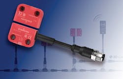
The SRF sensor from Bernstein is an especially compact device used to protect employees from hazardous areas that may produce injury during machine operation (Fig. 1). This is often done by shutting down or not starting up machines and equipment when the guarding safety device is not properly closed. When using keyed interlock devices, there is the concern of precise alignment as well as the time and effort needed for installation. Because of this, the use of non-contact magnetically-operated reed switches is very popular.
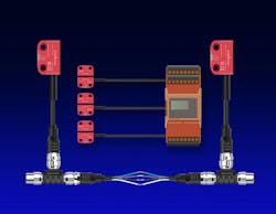
However, they also have their drawbacks. For one, reed switches are relatively fragile devices that can fail unpredictably either in an open or closed state, leaving hazardous areas unprotected. Also, in order to reach a higher safety level, reed switches often need to be wired individually to a special safety relay. Imagine using a half-dozen reed switches on one machine. The cabling alone creates a maintenance and installation challenge that isn’t necessary with the SRF non-contact devices, since they can be installed safely in series. These are only a few of the drawbacks that the SRF sensor has been able to solve.
The SRF designation is an abbreviation for Safety RFID. This particularly compact sensor protects employees from injuries by shutting down or not allowing the start-up of machines when the safety guard is not properly closed. The size of each unit is only 36.5 × 26.2 × 15 mm. Units are connected using an M12 pluggable system, including “T” connectors for series installation and provide a safety level of
PLe, Cat. 4 (according to EN ISO 13849-1) and SIL CL3 (according to DIN EN 62061). The transmitter, receiver, connectors, and wiring are suitable for wash-down processes, having an IP69 rating.
As a non-contact device, precision adjustment is not an issue (Fig. 2). With a rated distance of 13mm (10mm assured sensing ON; 25mm OFF) the SRF sensors offer a large alignment tolerance by providing 2 OSSD safety outputs (and diagnostic signaling) when the transmitter and receiver are within range. When considering equipment like robots and packaging equipment, this feature is a huge benefit because it allows machines that are subject to excessive vibration to operate without causing nuisance trips.
Industry 4.0 Diagnostic Capability
Particular attention has been paid to the diagnostic system that comes with the sensor. The idea was to include as much data collection capability as possible, making it available centrally and flexibly in order to aid in an intelligent production situation. Bernstein AG does this through the use of a Daisy Chain Diagnostics (DCD) system. The fact that diagnostic data can be fed into the machine control system from each sensor is a leap forward toward Industry 4.0 operations. The sensor diagnostics can be integrated using I/O Link or an I/O Link Mater with a gateway (such as Profinet or Ethercat), or else can be displayed on an Android-based smartphone or tablet through the use of NFC technology. (Near Field Communications is a smart-phone application that allows devices to exchange information simply by placing them near one another.)
All of the error messages are stored in the diagnostics module using a time stamp and can be retrieved via all interfaces if needed. Thanks to the NFC function, this important diagnostic information can be read even when there is no voltage on the diagnostic module. This unique feature allows efficient troubleshooting and accelerates restart of defective machines. Moreover, there is a fault memory which stores system-relevant data in order to simplify troubleshooting.
The primary benefits of having a diagnostics system available through the non-contact SRF sensor system includes access to comprehensive diagnostics information for each sensor and for the entire system; diagnostic data that can be retrieved easily; time and cost savings during commissioning, maintenance, and fault investigation; display of diagnostic data on smartphones via NFC; and simple troubleshooting through reading out the fault memory (Fig. 3).
Another very important feature is protection against unexpected machine stops through a pre-fault detection system, which provides a 20-minute warning prior to a complete shutdown. Here’s how that works: If an error is detected at one output, the sensor indicates this with a flash code while simultaneously transmitting the information via the diagnostic system. After the allotted 20 minutes, the functioning output will switch off.
Twenty different items of diagnostic information can be retrieved and made available for each sensor, whether through NFC or the series line. Basic information includes whether or not the actuator has been coded and detected, as well as several safety outputs, a local reset function to enable restart of the machine, and operating voltage warnings. Extended diagnostics include additional sensor functions such as coding levels and resets, the number of remaining actuator teach-in functions, a variety of output errors, sensor temperature, and more. As the diagnostic data is very extensive, it is divided into basic and extended information, which allows for simplified data processing when used with superior control systems.
The idea was always to create cost-effective predictive maintenance based on fault detection early in the process—and to prevent shutdowns. The more convenient this type of operation was, the more smoothly operations could continue without trouble. That’s why, if the power supply fails, a fault memory via NFC covers the troubleshooting. If a fault is detected at an emergency output, an emergency mode also offers the option to power the machine down in a controlled way before an emergency shutdown is triggered, ultimately preventing tool or work piece damage.
All of this detailed diagnostic data provides a complete status image of each sensor, even when designed into a multiple-sensor series arrangement to support smart production. Diagnostic data is fed into the machine control system via I/O Link. The diagnostic data delivers cost-effective predictive maintenance in the simplest way possible. Through its advanced fault tolerant recognition capability, costly machine shutdowns can be prevented.
The sensors are offered with three different coding levels. Low Level Coded sensors are activated with any SRF actuator. High Level Coded sensors are paired with one specific actuator. Unique Level Coded sensors can only be paired once. After pairing, the sensor cannot be activated with any other actuator. The pairing procedure does not require any additional equipment. Sensors with an individual PNP diagnostic output are also available. They can be wired directly to a PLC to indicate which door, gate, or guard is open or closed.
How RFID Sensors Work
An RFID (Radio-Frequency IDentification) system has three primary parts that allow it to do its job. A scanning antenna is used to send and receive signals; a transceiver (with a decoder) is used to interpret the data collected; and a transponder (or RFID tag) is used to relay specific information about the sensor itself.
To begin with, the scanning antenna delivers RF signals in a relatively short range and can perform two important functions. First, the antenna provides a means of communicating with the transponder, but it can also provide the RFID tag with the energy to communicate (in the case of passive RFID tags). This is a key part of the technology that is available today. RFID tags don’t need to use batteries for power. When using the antenna for power, they can remain usable for very long periods of time, making them maintenance-free for all practical purposes.
The scanning antennas can be permanently affixed to a surface of the device, taking on whatever shape is necessary for the application. When an RFID tag passes through the field of the antenna, it detects the activation signal from the antenna. This wakes up the RFID chip, so that it can transmit any information gathered on its microchip to be picked up by the scanning antenna.
In addition, the RFID tag may be one of two types. Active RFID tags have their own power source; the advantage of these tags is that the reader can be much farther away and still get the signal. Passive RFID tags, however, do not require batteries, can be much smaller, and have a virtually unlimited lifespan. RFID tags can be read in a wide variety of circumstances, whereas barcodes or other optically read technologies are useless. The tag need not be on the surface of the object, and is therefore not subject to wear. Also, the read time is typically less than 100 milliseconds, making it ideal as part of a larger control system. Finally, large numbers of tags can be read at once rather than item by item.


