Material fatigue is generally considered the most-common failure mode for welded parts and structures subject to dynamic loads and stresses. The two previous articles in this series delved into the basic principles and methods for predicting the durability of welded structures that bear fluctuating loads.
These articles established mathematical relationships between fatigue, stress range, and weld details. Now, in this third and final installment, we look at how the pertinent equations and fatigue data apply to real-world situations.
Miner’s Rule
Let’s look at two representative examples intended to demonstrate two different approaches for calculating fatigue life. One is simpler, more direct, and intuitive, while the other is more complex and less intuitive.
The first entails a single load case with one particular stress range repeatedly applied to one particular section of a member. As we’ll show, life can be calculated directly.
The second case involves multiple load cases producing multiple stress ranges applied to a specific welded structural section. To solve this problem, we need to use Miner’s Rule.
It is critical to remember that fatigue damage is cumulative. For example, many cycles of a smaller stress range may do as much fatigue damage (such as microscopic-to-macroscopic crack growth) as a few cycles applied at a relatively large stress range. However, if both of these representative cycles are combined at the same section of the same member, the damage from both load cases will accumulate.
Miner’s Rule is basically a simple mathematical model of the fatigue cumulative damage concept:
where i = a load case producing a known stress range (Sri) at a specific structural member section; k = the total number of load cases applied to that same section; ni = the number of cycles applied at a known stress range (Sri); and Ni = the theoretical fatigue life corresponding to that stress range (Sri).
This file type includes high resolution graphics and schematics when applicable.
Based on fatigue curves generated by the Transportation Research Board (TRB) National Cooperative Highway Research Program and the American Welding Society (AWS), and discussed in the first article:
Defining load probability, Pi:
Here, Q = the fatigue category coefficient for the member section being analyzed; N = the total number of cycles (in millions); and Pi = the percent frequency at which a given load case is applied.
Substituting these expressions into the Miner’s Rule equation gives the general cumulative damage fatigue life equation:
Note that total fatigue life (N) can be readily calculated from this equation if the various stress ranges (Sri) and corresponding load case frequency values (Pi) are known. The stress range can be calculated in at least two different ways:
• A single “fatigue load” (or “weighted” average load) applied at one or more locations (see the first example).
• Several specific loads applied at multiple locations (second example).
To find the fatigue load, Wa, rearrange the life equation as follows:
Therefore,
where Wi = a specific load applied at a particular frequency (Pi).
Similarly, the Crane Manufacturers Assn. of America (CMAA) Specification #74 quantifies fatigue load in terms of a mean effective load factor (ke):
with wi = ratio of each lifted load to rated capacity and Wmax = rated capacity.
This specification defines four useful Load Classes based on the value of ke:
• L1: Cranes which almost never lift rated load and normally lift very light loads (ke = 0.35 to 0.53).
• L2: Cranes which rarely lift rated load and normally loads of about 1/3 rated load. (ke = 0.53 to 0.67).
• L3: Cranes which lift rated load fairly frequently and normally loads between 1/3 and 2/3 of rated load (ke = 0.67 to 0.85).
• L4: Cranes which are regularly loaded close to rated load (ke = 0.85 to 1.00).
Applying Fatigue Data
Here’s a general procedure for fatigue analysis of welded structures.
• Calculate fatigue load based on load cases and probability.
• Determine dynamic load factors, if applicable.
• Determine sections of members to analyze based on high stress range, lower detail class, or both. In some cases, inspection alone is insufficient for determining the exact section that will suffer the most cumulative damage. In such cases, a chart or graph of data for multiple sections spaced at some acceptable interval may be necessary.
• Determine joint detail class/fatigue category of each member section to be analyzed.
• Calculate stress ranges for these sections using traditional engineering mechanics (statics and dynamics) techniques and strength-of-materials considerations.
• Calculate fatigue life for each applicable section of the member using Miner’s Rule relationships.
Thoughts on FEA Techniques
Readers of the previous articles in this series made some good comments about newer technologies in the study of fatigue in welded structures, although a few might be considered a little off base in reference to the “older” science—especially one statement about “assuming a notch factor to arrive at the stresses.”
Actually, the inherent beauty of the method outlined in this series of articles is that users do not have to determine a notch factor. Laboratory tests and corresponding fatigue curves are based on the base stress (or nominal stress) in a structural member, not the stress concentration at the weld joint being analyzed. This really is the best feature of this method; it’s analytically simple and requires much less time than an FEA study. No question, it gets users in the ballpark of fatigue life.
Many engineers are familiar with FEA techniques. We have done extensive research for a number of years in an effort to relate an FEA-obtained “stress concentration” to the fatigue life of a particular weld joint. While this is all worthwhile, the older “pre-FEA era” methods are still very useful in confirming the newer science. We always attempt to set our new engineering designs in the context of history.
Simple Loading
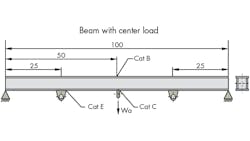
In the first example, a simply supported beam is a welded box section with longitudinal fillet welds parallel to the applied bending stress. The beam has a span of L = 100 in. and a section modulus, Z, of 21.0 in3. Three different loads (in magnitude)—W1, W2, and W3—are applied at three respective frequencies, but always at the same point: the center lug. Because loads are always applied at this same point, the problem is quite straightforward to solve. Simply by calculating the fatigue load (Wa), solving for the base stress at various points of interest, and directly determining the fatigue life at each of those joints, we can determine the fatigue life of the structure.
Of course, one can also use Miner’s Rule to solve this problem, even though it’s not required to determine the solution.
Given the following load spectrum, determine the fatigue life at the sections indicated assuming W = 0 when unloaded. Note that the fatigue categories discussed below are described in our first article. The America Association of State Highway and Transportation Officials developed a classification system for load-induced fatigue. Each category indicates the relative fatigue strength of certain types of welded constructions. They range from Category A (high fatigue resistance) to Category E (most susceptible to fatigue crack growth). The American Welding Society also includes this information in its publication AWS D1.1 Structural Welding Code - Steel.)
The load spectrum is as follows:
W1 = 12,000 lb @ P1 = 0.50
W2 = 18,000 lb @ P2 = 0.40
W3 = 24,000 lb @ P3 = 0.10
In other words, a load of 12,000 lb is handled 50% of the time, a load of 18,000 lb is applied 40% of the time, and a maximum load of 24,000 lb occurs only 10% of the time. As already stated, these percentages (probabilities) must add up to 100%, which represents a complete duty cycle for this particular welded steel structural member.
First, calculate the fatigue (weighted average) load:
Wa = (W13âP1 + W23âP2 + W33âP3)1/3
Wa = 16,600 lb
Next, find the base stress range values using basic mechanics of materials methods:
SrB = SrC = σmax - σmin = M/Z - 0 = (1/4)(WaâL)/Z - 0
where M is the maximum bending moment in the beam at section B/C.
SrB = SrC = σmax - σmin = (1/4)(16,600)(100)/21.0 - 0
SrB = SrC = 19.8 ksi
and
SrE = (1/2)SrB
SrE = 9.90 ksi
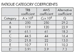
Now, find fatigue life at each section indicated. Obtain Q from the Fatigue Category Coefficients table. For the Category B section:
NB = (QB/SrB)3
NB = (22.9/19.8)3
NB = 1.5 million cycles.
For Category C:
NC = (QC/SrC)3
NC = (16.4/19.8)3
NC = 0.57 million cycles.
And for Category E:
NE = (QE/SrE)3
NE = (10.3/9.90)3
NE = 1.1 million cycles.
Therefore, the minimum theoretical fatigue life for this beam is about 570,000 applications of the given load spectrum. Predicted failure would occur first at the Category C section in the weld joint connecting the center lifting eye.
An alternative solution to this problem uses Miner’s Rule. For instance, life at the Category B section can be calculated as:
Sr1B = (1/4)(12,000)(100)/21.0 = 14.3 ksi
Sr2B = (1/4)(18,000)(100)/21.0 = 21.4 ksi
Sr3B = (1/4)(24,000)(100)/21.0 = 28.6 ksi
(NB/QB3)(Sr1B3â P1 + Sr2B3â P2 + Sr3B3â P3) = 1.0
Thus, NB = 1.5 million cycles, which completely agrees with the above results.
In the next example, the problem is more complex and Miner’s Rule is required to find a solution. In this case there are still three loads applied at three respective frequencies, but at three different points. In other words, each load produces a different stress level at any given section of the beam.
The beam is a welded box section with longitudinal fillet welds parallel to the applied bending stress and a section modulus, Z, of 10.5 in3.
Given the following separate load cases (that is, loads not applied simultaneously), determine fatigue life at the sections indicated assuming all Wa = 0 in the unloaded condition. Load cases for the Category B section are:
W1a = 3,000 lb @ P1B = 0.25
W2a = 4,000 lb @ P2B = 0.35
W3a = 6,000 lb @ P3B = 0.40
For the Category B section, all three load cases will contribute toward fatigue damage. Determine stress range values (Sr) for Category B section:
Sr1B = (3,000)75/10.5 = 21.4 ksi
Sr2B = (4,000)50/10.5 = 19.0 ksi
Sr3B = (6,000)25/10.5 = 14.3 ksi
Find fatigue life at the Category B section using Miner’s Rule:
(NB/QB3)(Sr1B3â P1B + Sr2B3â P2B + Sr3B3â P3B) = 1.0
NB = 2.0 million cycles.
For the Category C section, only two load cases (W1a and W2a) contribute toward fatigue damage. Their respective load probabilities are calculated proportionally as:
P1C = 0.25/(0.25+0.35) = 0.42
P2C = 0.35/(0.25+0.35) = 0.58
Load cases for the Category C section are:
W1a = 3,000 lb @ P1C = 0.42
W2a = 4,000 lb @ P2C = 0.58
Find stress range values (Sr) for Category C section:
Sr1C = (3,000)50/10.5 = 14.3 ksi
Sr2C = (4,000)25/10.5 = 9.52 ksi
Find fatigue life at Category C section using Miner’s Rule:
(NC/QC3)( Sr1C3â P1C + Sr2C3â P2C) = 1.0
NC = 2.6 million cycles.
For the Category E section, only one load case (W1a) contributes toward fatigue damage. Thus the load probability for that load case is simply 1.00. The load case for the Category E section is:
W1a = 3,000 lb @ P1E = 1.00.
Thus, SrE = (3,000)25/10.5 = 7.14 ksi
and (NE/QE3)(Sr1E3â P1E) = 1.0.
NE = 3.0 million cycles.
Therefore, the minimum theoretical fatigue life for this beam is about 2,000,000 applications of the given load cases. Predicted failure would occur first at the Category B section—most likely in the weld joint connecting the beam's flanges and webs.
This file type includes high resolution graphics and schematics when applicable.


