This article was updated April 12, 2023. It was originally published Feb. 3, 2016.
Blind rivets, also called pop rivets, are commonly used to hold components together more efficiently and reliably than screws, bolts or nuts. They come in a variety of sizes and are widely used in electronics, aerospace, ship building and a host of other industries.
Although blind rivets are fairly simple and relatively easy to install, there are four simple rules engineers should adhere to when using them in their designs. Here are those rules and some tips on following them.
Select Setting Tools Carefully
How the rivets will be installed is critical, and getting the right installation tool or setter is the first step. The main issues to be resolved when selecting riveting tools include power and air pressure ratings and type of nosepiece needed.
Once the right tool is chosen, tool clearance should be the next consideration. For example, distances from walls or projections to the rivet centerline should be checked to determine if the tool will fit—that is, if enough clearance (or room) is available.
Clearance should also be checked if the rivets are going to be set from the inside of a channel or cylindrical section. Angles and formed sections can also interfere with installation.
In some cases, technicians can solve the problem by using a nosepiece extension; it can add an inch to the setting tool’s reach. Another solution is to set rivets from the unobstructed side, if there is one. Or designers can shorten the angled section, increase the angle and open it up, or both.
Design for Strength
Companies that make blind rivets usually recommend specific hole sizes for their rivets. These recommendations should be followed closely to get the most strength, maximum pull-up and best hole fill from the rivet.
READ MORE: Blind Rivet Bolt Combines Screw and Nut for Faster Assembly
If hole alignment is a problem, put a slot in the joint where it will face the setting tool and put a hole of the recommended diameter in the second, lower material. This will give the finished joint its maximum strength.
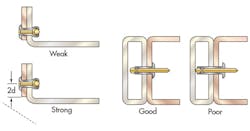
Another key to maximizing strength is to ensure parts are properly mated. For example, when a tube is joined to a flat sheet or beam, setting the rivet against a section of tube that is flattened creates the most rigidity. A slightly less rigid, but still satisfactory, joint can be made without flattening the cylinder. However, installing the rivet through both of the tube’s walls creates a weak joint.
Blind rivets exert high forces when clinched, so rivets should never be set against cantilevered joint extensions. Small gaps between parts being joined are all right if both parts are supported on both sides of the gap. And installing rivets on both sides of the gap creates a rigid joint, but it is generally unnecessary.
Combining Materials
Blind rivets are commonly made of aluminum, steel, stainless steel, Monel and copper. For maximum strength and minimum corrosion, rivets should be made of materials that match the materials of the parts being joined.
Compressible (soft) materials do not provide a firm base for clinching blind rivets. In such cases, it’s best to add support. One technique is to put a washer against the compressible material, with the rivet head on top of the washer. To eliminate the washer, designers can specify a rivet with large flange just beneath the head and the compressible material just beneath the flange.
Rivet Length
The rivet should have the right length to be compatible with the joint’s thickness. Blind rivets should always have a grip range that spans the thickness of the parts being joined. Actual rivet length is longer than the grip range. If the rivet’s grip is too short, you end up with a weak joint. If it is too long, the rivet’s cost will be unnecessarily high, plus the rivet will be more likely to interfere with blind-side clearance.
Blind-side clearance is the distance between the underside of the rivet head to the end of the mandrel before setting. It does not include the combined thickness of the parts being joined. If there isn’t enough clearance, the rivet cannot be set properly.
For the strongest joints in corners, the clearance between the rivet centerline and the edge of the material being joined should be at least two rivet diameters. If joint strength is not critical, this clearance can be greatly reduced, especially when rivets are primarily used for positioning rather than strength.


