This file type includes high resolution graphics and schematics when applicable.
Tests of golf clubs and other sports equipment—whether carried out by their designers and manufacturers or the organizations that govern the various sports—take time and money. But could FEA replace all (or at least, most) of the testing currently done on sports gear? Would it give accurate results even when testing involved high-speed impacts, such as a golf club smacking a 200-yard drive, a bat hitting a home run, or a tennis racket serving a 100-mph ace? Those some of the questions researchers at Veryst Engineering LLC outside of Boston were looking for in its recent simulation experiments and study of golf balls.
Setting Up the Study
Veryst engineers, with help from the U.S. Golf Association (USGA), decided to take a look at what current simulations and FEA could do in terms of accurately replicating the physical testing of golf balls.
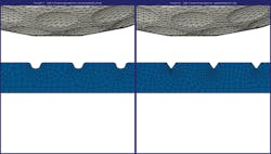
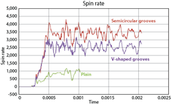
USGA provided data it had collected from exhaustively testing a variety of balls. It had tested conventional balls—ones the average player would use, not expensive and exotic high-end ones. USGA researchers used its golfing robot, Iron Byron, to consistently hit balls with the same force, velocity, and club-head angle at impact. They ran at least three series of tests using different types of club heads: one with a flat face, one with vee-shaped grooves, and one with round-bottomed grooves. They used high-speed cameras of each stroke and impact to measure the ball’s speed and its rate of spin or rotation. They also calculated how long the impact lasted (only a few milliseconds).
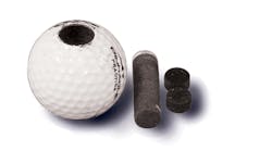
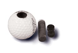
At Veryst, engineers were preparing to simulate that impact. The first step was to get an accurate and representative model of a golf ball—data the USGA did not have. So the team took core samples of several golf balls, dissected them, and then carried out a detailed engineering post-mortem. All of the balls were constructed similarly: a polymer core surrounded by several thin layers of plastic and other materials. They also shared a dimple pattern on the hard, white outer covering.
The team took thin, penny-sized samples of each material and put them through a few material tests. In one, samples were compressed relatively slowly compared to the speed at which the materials would get compressed in an actual impact. The samples were compressed until they reached a specified amount of deformation, with the test instrumentation recording the force involved.
In another test, a Split-Hotkinson pressure bar—also known as a Kolsky bar—large, fast impulse loads were applied to samples to get measurements of how the materials reacted and deformed. In this instrument, a sample is placed between two bars, a transmitted bar and an incident bar. A stress wave created at the end of the incident bar away from the sample travels quickly down that bar and toward the specimen, where it splits into two waves. One wave travels through the specimen and into the transmitted bar. The other wave gets reflected back up the incident bar. Strain gauges on both bars and specimen measure changes in the strain waves as they pass through them. The strain data caused by the incident, reflected, and transmitted waves lets technicians determine the stresses and strains in the specimen.
The vast majority of engineering schools and most companies lack this expensive research tool, according to Veryst. “But it’s important to conduct such tests because materials react completely differently when loads are applied quickly rather than slowly,” says Jorgen Bergstrom, a principal engineer at the firm. “In fact, results from the Split Hotkinson tests showed that many of the materials used in the multi-layer golf-ball cover behave non-linearly in response to forces when those forces are applied very fast.
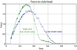
“Many engineers are unaware that the materials used in some of the layers of the golf ball behave extraordinarily different at high impact velocities than they do to slow ones,” Bergstrom continues. “So if they carried out conventional mechanical testing, which is done relatively slowly compared to an impact, they could mistakenly assume that is how the material will behave in fast impact events. In fact, material properties can differ by a factor of 10 from what the slow-rate data would indicate. It takes insight to realize this or experiments to verify it.”
For impacts, Bergstrom considers a slow-rate event to take seconds to complete while a fast-rate event is over in a few milliseconds.
The project would also require good models of the three types of club heads. The engineers determined that the head was much stiffer than the ball and that deformation would affect the ball to much higher degree than the head. This let the researchers concentrate on the shape of the club head and the pattern of grooves, simplifying the model of the head. “We did not try to evaluate or include grooves of different sizes or shapes or the spacing between them,” notes Bergstrom. “We focused our efforts on modelling the ball and just the shape and grooves of the head.”
This file type includes high resolution graphics and schematics when applicable.
Proving the Models
This file type includes high resolution graphics and schematics when applicable.
With material data in hand, Veryst began modeling the two components for the simulation. For the head, they used straightforward CAD software. But for the ball, they relied on used Python scripting software that could automatically mesh the model for FEA.
“The ball’s geometry is simple: a series of spherical shells of different materials,” says Bergstrom. “The challenge with the ball, however, was its outside surface. It contains several hundred dimples that determineThe Python software let the team quickly create a mesh and easily alter the model and surface pattern. So in the future, others can look at whether it makes a difference on balls speed and rotation if the dimples are larger or smaller, or closer or father apart.
To ensure the mesh was not too coarse, which would mean the results were not valid, or not too fine, which would lead to excessively long run times for the FEA software, a mesh refinement study was carried out. It starts with a coarse mesh and finer meshes are used in flowing FEA runs. When addition fineness, which translates into ever smaller elements, does not change the results significantly, the mesh is considered optimal.
Running the Analysis
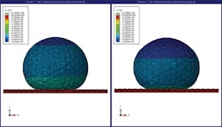
With the models and mesh in places and the actual results from the USGA in hand, Veryst ran the impact simulations. But because the impact event was quick and the ball’s materials did not react linearly during testing, the team decided to use more than one type of modeling program.
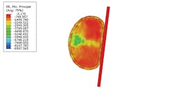
“Engineers might assume that in the impact between a golf ball and club, the material in the ball deforms uniformly, but that is not the case,” notes Bergstrom. “Some regions of the ball will experience more deformation and strain than others. So even if the actual duration of the impacts is short, the range of deformation and strain rates will very throughout the ball. The key is to have a model that captures the influence of how different strain rates influence the ball’s response.”
The team decided to use the linear viscoelastic model (LVE) and the parallel network model (PNM). LVE is a simplified model that recreates a materials viscoelastic behavior by modeling it as a network of springs and dampers. One drawback of the LVE is that the deformation and strain, as well as their rates of change, must remain in a relatively narrow range. If they do not, then the material response to the impact is nonlinear. “This makes LVE often good enough for experiments,” says Bergstrom. “But it is not as good or accurate with non-linear events and those that happen very quickly.” The team also ran the simulation using a parallel network model (PNM). It recreates a materials behavior using a similar network of springs and dampers, but they have nonlinear responses. This lets them recreate highly nonlinear plastic behaviors.
The PNM can provide exceptionally accurate predictions of the behavior of material models, even if those materials are anisotropic viscoelastic polymers. The model’s main limitation is that it can take some time for an engineer to fully understand how best to structure it for a new material. PNMs also take more time and effort to set up and run because they require accurate information on stain rates at different levels of deformation, and this means more data gathering.
In this study, using PNM meant Bergstrom had to reverse-engineer the ball and determine the composition and properties of each layer. “But once you do the reverse engineering,” says Bergstrom, “you have all the data you need to carry out a long list of other experiments and simulations.”
Results and Conclusions
Data from the PNM simulations matched the USGA experimental data quite closely. The LVE results also mirrored the experimental data, but were much less accurate than the PNM data. The results also showed a close match between experimental data for grooved and flat heads and the simulation results for those different club heads.
“Our study seem to indicate that computerized models, simulation, and FEA—or virtual testing—will let engineers cut corners in investigating some material behavior issues,” says Bergstrom. “For example, it can eliminate some physical testing, which saves money and time. It also gives designers a powerful tool that will let them investigate all kinds of parameters. We just scratched the surface in this study. We could use the information we have to look more closely at club head, club design, or club h-head velocity.”
Virtual testing could also let engineers gain insights into parameters and phenomenon that are hard to measure experimentally. “For example, what if a designer wanted to know how much energy is dissipated during the impact between ball and club?” asks Bergstrom. “That is hard to measure in an actual experiment because the energy dissipates in several forms and ball covers behave non-linearly. But we can get that data directly from a simulation like this one.”
This file type includes high resolution graphics and schematics when applicable.
