Ensuring Parts Fit, Using Bonus Tolerance to Your Advantage
This article has been updated on May 2, 2025.
What You’ll Learn:
- Designers can use ASME Geometric Dimensioning and Tolerancing (GD&T), an internationally recognized symbolic language, to describe the acceptable limits of part feature variance.
- Although coordinate tolerances allow designers to quickly prepare drawings for manufacturing, there are several hidden drawbacks and cost implications that accrue over time. How can designers overcome these drawbacks?
- What is bonus tolerance? Why would a designer want its benefits? And when is bonus tolerance applicable?
Avoiding Tolerance Headaches
In manufacturing, the devil is in the details—and the smallest oversight can lead to big headaches. Too often, it’s 4:30 p.m. on a Friday, you find out your trusted machinist is away on a fishing trip, and a tolerance stack-up is preventing parts from assembling correctly, delaying or even stopping production. We’ve all been there.
The good news: There is a better way to ensure parts assemble than relying on traditional ± tolerancing schemes. Designers can use ASME Geometric Dimensioning and Tolerancing (GD&T), an internationally recognized symbolic language that is defined in the ASME Y14.5 standard (2018, most recent version) to describe the acceptable limits of part feature variance.
GD&T is a powerful and expansive topic; thus, this article will focus on only a single foundational concept: bonus tolerance. More specifically, we’ll discuss how to take advantage of bonus tolerance, when used with GD&T positional tolerancing to improve product and fixture design, reduce machining cost and improve assembly—especially when dealing with hole positions in volume production.
If you’ve been on the fence about using ASME GD&T, this use case could be an appealing first step.
The Designer’s Dilemma
Upon completion of CAD design work, a typical designer’s task is to translate the theoretically perfect 3D CAD model into a 2D drawing conveying the mating functional interface and manufacturing tolerance requirements. Should they use a quick and easy coordinate dimensions with traditional (±) tolerancing scheme, or the more thorough and precise—but also more involved—language of GD&T? This decision is based on several factors including, but not limited to:
Prescribed Practice
- Contractual requirements
- Established internal engineering drawing practices
Designer’s Discretion
- Required precision and accuracy
- Production volume
- Cost of rework or replacement
Team Skills
- The designer’s skill in understanding and applying GD&T relative to part complexity or function
- The manufacturing team's ability to interpret and make the product per GD&T specifications
- The quality team’s ability to interpret and inspect against GD&T specifications.
± Tolerances: The Expensive Shortcut
Although coordinate tolerances allow designers to quickly prepare drawings for manufacturing, there is no “free lunch,” and there are several hidden drawbacks and cost implications that accrue over time. Among them:
1. Non-GD&T drawings inadequately describe the functional relationships between features.
2. Tolerance “stack-up” issues arise, increasing the chance of assembly issues that cannot be resolved by simple rework, thus resulting in high scrap rates and production delays.
3. ± Tolerance schemes result in square shaped tolerance zones for hole and pin positions (e.g., for fasteners, dowel pins, bearings, etc.) which are 57% smaller than the cylindrical tolerance zones available when applying positional tolerancing using GD&T.
4. Naturally, to minimize risk, designers using ± tolerancing often specify tighter tolerances than functionally necessary (forgoing a functional tolerance stackup analysis) to “feel” more confident that parts will fit and function as depicted in the CAD environment with minimal post-manufacturing intervention, but while increasing cost in several important but neglected ways in many organizations:
- Use of more precise, fragile, expensive cutting/drilling tools
- Slower setup and multiple tool changes
- Slower feeds and speeds
- oMore complex inspection setups and procedures
Bonus Tolerance: When Deviation is an Advantage
The concept of bonus tolerance is only applicable when you have features of size (e.g., hole/slot or a shaft/tab) controlled for location and/or orientation by geometric tolerances (e.g., tolerance of position or perpendicularity) and either the maximum material condition modifier (MMC) or Least Material Condition (LMC) modifier. If there is no (M) or (L) modifier next to the geometric tolerance, there is no bonus tolerance. Note: A hole is at MMC when the hole is the smallest acceptable size.
READ MORE: Avoiding Problems with Dimensional Tolerances
Conversely, a shaft or pin is at MMC when it is the largest allowable size. The purpose of the MMC modifier is to ensure and convey the function of assembly so that mating parts like pins and holes, or tabs and slots will fit together even when produced at their worst-case tolerance for assembly (e.g., largest pin into smallest hole, and widest tab into smallest slot). Bonus tolerance is the additional tolerance of location and/or orientation that becomes available when a feature of size deviates from its’ MMC or LMC (depending upon which modifier is applied).
Why would a designer want the benefits of bonus tolerance? Typically, a designer wants to ensure parts will assemble while specifying the largest tolerance possible to reduce manufacturing costs. One interesting note is that the concept of bonus tolerance isn’t explicitly mentioned in the ASME Y14.5 standard but rather is a consequence of the GD&T strategies outlined in this article.
When to Use Bonus Tolerance
For simplicity’s sake, we will focus on the commonly used practice of specifying a hole position tolerance with an MMC modifier. This communicates the function of assembly vs. absolute position, and that the location tolerance of the hole is tightest when it is produced at its smallest allowable size. As this feature deviates from MMC (larger hole within allowable size limits), bonus tolerance allows for more positional tolerance, because the assembly will still work. In essence, a larger hole allows more positional variance while allowing the fastener to pass through as intended.
Conversely, when a hole position tolerance is used with an LMC modifier, this communicates the function of thin wall protection vs. centering or assembly, and that the location tolerance of the hole is tightest when it is produced at its largest allowable size. A typical application is when the designer wants to ensure that the inner diameter and outer diameter of a thin-walled bushing or boss and hole surfaces don’t get too close to each other, resulting in structural weakness or a breakout condition.
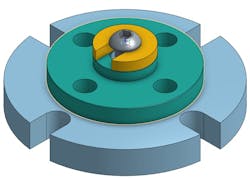
Applying the Concept: Flange Bolt Circle
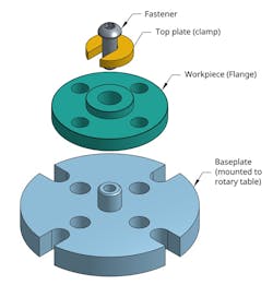
Drilling a bolt circle for a volume run of precision flanges is an application that demonstrates the potential of the MMC (M) bonus tolerance concept. In this example, let's assume the fixture is mounted to a rotary table on a manual knee-style milling machine (e.g., a Bridgeport) to perform the drilling operation.
The fixture’s purpose is to:
- Orient and locate the flange based on the specified functional datum features of the part, typically the flange’s mating face (datum feature A), and its central hole (datum feature B in the example below). This ensures that the bolt circle is positioned relative to the flange’s functional features;
- Securely clamp the flange to prevent movement during the drilling operation;
- Provide clearance for the drill bit as it passes through the flange, providing space for chip evacuation and coolant passage.
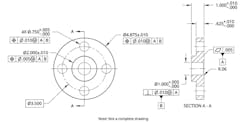
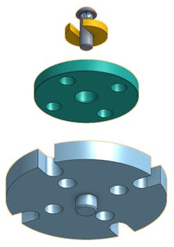
Because the flange designer specified the hole position using position tolerance with an MMC modifier, the fixture does not need to precisely locate the individual holes in the pattern: It simply needs to accurately orient and locate the part to the specified datums on the flange. As the actual size of each hole deviates from their MMC size, their available positional tolerance increases. The fixture can have oversized holes (as shown below) to provide drill bit clearance and accommodate the additional position variance allowed through bonus tolerance.
The net results of bonus tolerance include:
- A less costly fixture to design and manufacture
- Less scrap, as more parts will fall within the larger GD&T tolerance zone
- An awareness of bonus tolerance that can allow the machinist to work faster, spend less time on setup and thereby increase throughput
- Inspection that can be done with a functional gage that simulates the flange and mating part at its worst-case condition, instead of more costly techniques (dial gages, calipers, optical comparator, CMM, scanning, etc.).
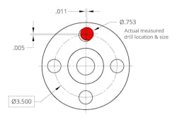
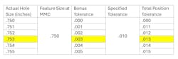
Is this hole location within specification? To calculate bonus tolerance:
Bonus tolerance (hole): BT = actual feature size – MMC size
BT = .753 - .750 = .003
Total position tolerance: TPT = specified position tolerance + bonus tolerance
TP = .010 + .003 = .013 (the acceptable tolerance zone size)
Actual diametric deviation =
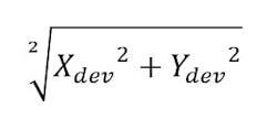
Actual deviation =
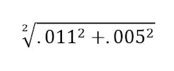
.012 < .013, thus the part is still within the tolerance zone.
In a volume production, the hole size and location will vary depending on multiple factors, including tool wear and machine backlash. As shown in the table below, the amount of total position tolerance will vary depending on the actual hole size.
Here is one possibility (amongst many possibilities) of a simple jig fixture design that would enable the machinist to drill the holes quickly and accurately. The base plate of this fixture has a locating feature that fits into the pilot hole for the rotating table. The base plate also has a locating boss for the flange through hole (datum feature B).

Starting Your GD&T Journey
If you are relatively new to GD&T or simply looking for the right upskilling opportunity to progress from coordinate tolerancing, a good place to start is to familiarize yourself with the ASME Y14.5-2018 standard. The foundational GD&T knowledge you need to effectively apply bonus tolerance in your product and fixture design drawings include:
- Regular features of size: What shapes constitute them (e.g., hole, shaft, pin, etc.)
- MMC and LMC modifiers: Essential for enabling bonus tolerance
- Datum Reference Frames: How to establish the coordinate system for a part
- Positional Tolerancing: How it can be used to control orientation and location relative to datum reference frame
- 1D tolerance stack: Simple worst-case analysis for single hole and fastener
- Bonus tolerance calculation: BT = actual feature size – MMC size (or LMC size)
- Total position tolerance: TPT = specified position tolerance + bonus tolerance
- Functional fixtures and gages: Their purpose, design and use cases.
GD&T: A Strategic Commitment to Manufacturing Excellence
The shift from coordinate tolerancing to GD&T can seem intimidating, but the benefits are clear, particularly as a designer understands how to leverage powerful concepts like bonus tolerance. This article only touched on a minute aspect of the breadth of capability ASME GD&T offers designers to communicate both functional and manufacturing requirements with the largest allowable tolerances.
READ MORE: Dimensions, tolerances, and more right on the model
At the core, GD&T is a symbolic communication language, and thus is most valuable when designers, machinists and quality personnel can discuss and achieve a shared understanding of the product’s functional requirements, manufacturing requirements and inspection setups. Position tolerance in conjunction with the MMC modifier has many different applications in product and hardware design and is just one possible example of a practical first step into the world of ASME GD&T, giving you the “wiggle room” needed to avoid Friday afternoon fires.
About the Author
Israr Kabir
Director of Emerging Technology, Strategy Office, The American Society of Mechanical Engineers (ASME)
Voice Your Opinion!
To join the conversation, and become an exclusive member of Machine Design, create an account today!

Leaders relevant to this article: