Lessons in Machine Vision: Eye on working distance and depth of field
Working on a machine vision project requires understanding each part of the system, including light sources, frame grabbers, computers, and perhaps most important of all, the lens-camera combination. With regard to lenses, it's vital to understand how application parameters such as field of view, resolution, working distance, and depth of field work together to determine vision system requirements. Here we will take a look at working distance and depth of field, how they help determine the right system specifications, and why the industrial environment affects component choices.
Working Distance is the distance from the front mechanical surface of the lens housing to the object's visible face.
Depth of Field is the depth of the object that is in acceptably sharp focus. If the object moves with respect to the camera, the depth of field influences the range of acceptable motion.
Working distance and depth of field requirements affect the lens and potentially the camera options for a given application. Once chosen, these vision-system components determine system specifications — primary magnification, focal length, and f-number.
Primary Magnification is the ratio of image size to object size. Since most motion control applications involve objects that are much larger than the camera's image sensor, primary magnification (PMAG) is usually much smaller than unity. PMAG for a vision system is typically calculated as the horizontal sensor size divided by the horizontal field of view.
Focal Length indicates how strongly the lens bends light to form an image. Usually shown as f in equations, it is the distance from the rear principal plane of the lens to the focus point when imaging an object infinitely far away. A lens has two principal planes, front and rear, which are theoretical planes used by optical engineers during lens design and analysis. For thick and multi-element lenses, the principal planes are usually somewhere in the middle of the lens.
f-number or f/A describes the image-space cone of light for an object at infinity. Lenses with low f-numbers are sometimes referred to as fast lenses and can collect more light than higher f-number lenses. For a lens designed to work at finite image and object distances, optical engineers use working f-number (f/Aw), which takes into account lens magnification.
Going the distance
Working Distance defines the space in which the optical system must work. Defined by the application, working distances generally get longer when objects are large, if they move through large distances, or if they need to be distanced from the camera for safety or environmental reasons.
If, for example, the object resides in an ultra-high vacuum (UHV) chamber, the camera will probably have to mount outside the chamber and look through a window because most cameras are incompatible with UHV. In such a case, the minimum working distance is the distance from the window to wherever the object mounts in the chamber.
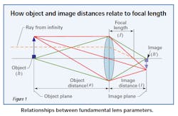
Figure 1 illustrates the concept of working distance. To simplify the drawing, a simple, single-lens model is shown in place of a more typical multi-element video lens.
In Figure 1, working distance is measured from the lens to the object and in this case is equal to the object distance; the image distance is measured from the lens to the image plane or camera sensor. In a real model, these would be measured from the front and rear principal planes respectively. For simple lens systems, basic equations can be useful in relating these parameters. For example, what is often called “the lensmaker's equation” relates the focal length to the object and image distances:
When viewing far away objects — o >> f — the working distance is effectively at infinity and the lensmaker's equation reduces to the following:
However, many machine vision applications require finite working distances and an associated magnification (m), as shown here:
where h' is the image height and h is the object height.
As the working distance changes, so does the image distance. This, in turn, increases or decreases the magnification. The lensmaker's equation shows that for a fixed focal length lens, increasing the working distance will shorten the image distance.
Sometimes, optical engineers increase the image distance by inserting spacers between the lens and camera. This reduces the working distance in an effort to restrict the field of view, thereby increasing the primary magnification. However, pushing a lens outside of its design parameters can lead to image degradation and possible illumination non-uniformity.
Exploring depth of field
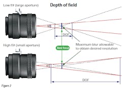
Figure 2 shows the geometry responsible for depth of field (DOF). Within theoretical limits, the object is only “in focus” at one specific working distance. Real systems, however, can tolerate some blurring of the image, identified by the “blur angle.” This blur angle relates to the system's resolution as discussed in the second part of this article series.
Any feature located within the DOF will then appear with acceptable sharpness.
For all practical purposes, the iris control of the lens adjusts and sets its DOF capabilities. As a general rule, the DOF of the lens is lowest at its most open setting. The most open position of the iris is associated with the lens' lowest f/A. On the other hand, if you decrease the diameter of the lens aperture, you will increase the f/A thus increasing depth of field. This is also called “stopping down the lens” and is illustrated in Figure 2. Photographers have been taking advantage of this relationship since the mid-1800s.
But increasing the f⁄/A has a couple of important implications. The first is a reduction in image brightness. Photographers compensate by increasing their exposure time by the square of the aperture stop change — for example, quadrupling the exposure time when changing from f/5.6 to f/11. Because vision-system image sensors are generally much more sensitive than even the fastest photographic films and engineers generally are able to flood the scene with as much light as necessary, this is seldom a problem.
The other implication is that lens performance falls off at higher f¼# settings due to diffraction. Diffraction limits how well light focuses on the image plane and occurs because of the wave nature of light. Diffraction limits cannot be overcome, so having realistic application goals and choosing a lens that is well suited to meet them is very important.
Image quality and depth of field are also affected by the design and manufacturing of the lens. Consult the lens manufacturer regarding details of this nature. It is important to note that as the object moves farther away from best focus, both contrast and resolution suffer. Therefore, depth of field should be specified at both a specific contrast and resolution if possible.
Environmental and other concerns
One major concern is keystone distortion, which is a geometric distortion inherent in traditional imaging systems. When imaging an object with depth, features closer to the lens appear larger than those of similar size farther away. It is possible, however, to eliminate keystone distortion by using a telecentric lens.
Other factors that arise in lens selection are mechanical constraints and environmental issues. Generally, longer focal length lenses are larger in both length and diameter than those with shorter focal lengths. This often leads to greater weight, which, in turn, means that more robust and heavier mounting structures are required. These comments apply equally to enlarged lens apertures and longer working distances.
Environmental considerations affect both system performance and system health. For example, the biggest single killer of vision system operating performance is lighting variations. Every vision engineer, consultant, and component salesperson has a stock of horror stories where intermittent system failures were traced to environmental lighting variations that the original designer failed to anticipate. Generally, the best plan is to build a light-tight enclosure around every vision system to isolate it from quirks like an odd sunbeam or overhead-light blowout.
Additionally, industrial facilities are notoriously challenging, vibration filled, and otherwise unfriendly to instrumentation. Dust, dirt, and solvent splashes, including water, can do untold harm to optical components. It may be tempting to think that periodically wiping dust from lenses is all that is needed. Unfortunately, not all dust is the same, and some dust will scratch optical surfaces.
To further complicate matters, some solvents used with the intent to clean components can have undesired affects. Acetone will dissolve modern, lightweight lenses and some other cleaning solutions will leave streaks if not used properly. Water that gets into the cavities of multi-element lenses tends to form a permanent fog on optical surfaces. Worse yet, it can also corrode or otherwise damage delicate internal structures.
Fortunately, there are two solutions to environmental problems. The first is to add enclosures and shields to protect cameras and lenses. Mounting the lens and camera in a lucite or polycarbonate box is an inexpensive way to shield it from dust and solvent splashes. To protect the lens face, take a hint from professional photographers who often keep a relatively inexpensive UV protective filter on their expensive lenses at all times. If anything undesirable happens, the filter takes the brunt of the damage while protecting the optical surfaces behind it.
The second solution is to specify lenses designed to defy the effects of environmental hazards. Harsh-environment optical components designed to resist the perils typical of industrial environments are a good choice in many applications.
For more information, contact Edmund Optics at (800) 363-1992 or visit edmundoptics.com.


