This file type includes high resolution graphics and schematics.
Force sensors weigh freight on manufacturing and transportation equipment. They also monitor loads on machines subject to stringent safety standards — such as mine lifts, construction cranes, industrial tanks, grain silos, and locomotives — to ensure equipment isn’t overloaded.
At the core of force sensors are load cells, transducers that convert force into measurable electrical outputs. There are hydraulic, pneumatic, piezoelectric, and capacitive load cells. However, strain-gage-based load cells are most common. These have fine wires (to 0.02 mm in diameter) made of steel, aluminum, or beryllium-copper alloy. The wire adheres to a thin paper or plastic base in one continuous zigzag that magnifies the effect of material changes in the wire in response to external loads. Leads at the beginning and end of the zigzagging wave connect to circuits.
Often, four strain-gage sensing elements are bonded to a machined housing in a Wheatstone-bridge arrangement. When subject to force, this array develops strain that changes the wires’ resistance and that triggers a change in electrical output.
Force-sensor types
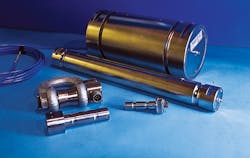
The most-common force sensors based on strain gages are load pins, shear beams, and tension links.
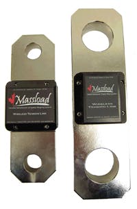
Tension links: Tension links, also called a tension cells, consist of two steel padeyes and a center body housing the load cell. They measure the force in cables, chains, and pulleys, and are most common in lifting, pulling, and winching applications on cranes and wire tensioners on safety cages used in mines. Standard tension links measure 25,000 to 100,000 lb, though custom versions can measure more.
Load pins: These substitute for structural pins anywhere there’s a need to know shear force. Typically, a beam is machined to be almost completely hollow (like a pipe) save for one segment with a solid cross section. Sensing elements mount on this remaining wall of material (also called a web). The pipelike body of the load pin withstands bending stresses while the solid cross section withstands vertical and horizontal shear stresses. The web’s strain gages measure these shear stresses. Standard capacities exceed 20,000 lb, though custom pins go higher.
Installation requirements
Tension links, load pins, and shear beams are rugged but must be precisely installed. Their load cells deflect predictably only when properly aligned to the applied load and surrounding machinery. Otherwise, skewed loading and moments cause incorrect readings, and oversupported load cells yield less than their expected outputs.
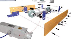
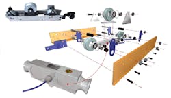
For accurate readings from shear beams and load pins, use the brackets and pins that come with them. Where applicable, carefully choose fasteners. For example, a design may need countersunk bolts to secure the sensor to the machine, especially if the heads are at risk of being sheared off by nearby equipment during operation.
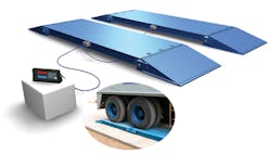
Also support the force sensors correctly. Unsupported ends of single-ended shear beams should be unobstructed. Double-ended shear beams should not be installed under tension or forced into spaces that degrade weighing accuracy. Where shear beams are used in tandem (on large cattle or truck scales, for example) scribe lines make it easier to level the beams to the same elevation. Loading-direction arrows printed on load sensors also help installers, particularly with symmetrical and sealed load pins (which make it difficult to know which way to mount them in a piece of equipment).
Output and display
Usually the sensor-to-readout signal type is only important to the machine builder, not end users. Many load cells send signals through hard-wired connections. These generally transmit industry-standard millivolt/volt signals because most weight indicators can handle this signal type. Elsewhere, load cells transmit output signals wirelessly. Wireless interfaces can connect nearly any load cell to nearly any display. Two other options for nonstandard weight indicators are 4-to-20-mA and 0-to-10-V interfaces.
Stand-alone readouts just show the weight measured. In contrast, portable PCs collect load-cell measurements and store and share that data locally or over the Internet. Full industrial controls take it further and spur machine responses based on collected load-cell data.
Custom-design tips
Off-the-shelf load cells and tension links go into machines when their integration is planned early in design. However, many load cells, load pins, and tension links are retrofits customized to fit existing systems — typically to enhance machine safety or performance.
When specifying a custom force sensor, carefully review its CAD and FEA models and the stress patterns they predict. Sometimes software presentations of a load cell are misleading: For example, a stress concentration that looks artificially high in one area may mask a stress pattern in another area. A mistake as simple as modeling with the wrong support constraints can inflate load-pin results. If testing doesn’t catch the error, components may not perform at their stated capacity.
Also look for documentation of a force sensor’s initial calibration. Reference cells in test devices must be traceable as outlined by National Institute of Standards and Technology (NIST) standards. Some suppliers comply with the Verified Conformity Assessment Program (VCAP), a National Conference on Weights and Measures track that certifies designs in North America. If VCAP applies, get the auditor’s report. When warranted, some vendors also verify results with those from third-party engineering firms. Complex or mission-critical applications require such quality assurance most often.
Edited by Elisabeth Eitel
Resources: Massload Technologies Inc.
Verified Conformity Assessment Program
This file type includes high resolution graphics and schematics.
