Demand for low-cost, robust motor drives has spurred increased use of sensorless vector control of induction and BLDC motors — in everything from consumer products to industrial applications, in myriad sizes and power ratings.
Sensorless vector control, also known as field-oriented control, outputs performance comparable to that of a motor drive using position/velocity feedback — in turn decreasing drive-system cost.
Some applications require a compact design; others in corrosive, extremely hot, or otherwise hostile environments necessitate that designs be free of additional wiring (for sensors or devices mounted on the shafts and so on.) Sensorless vector control benefits designs in both of these situations.
This month's handy tips provided by Dayong Tong of Parker Hannifin Corp., Electromechanical Automation Div., Rohnert Park, Calif. For more information, visit parkermotion.com.
Q&A
How does it work?
Control of electrical motors without position or velocity sensors usually utilizes one of three methodologies: Constant volts per hertz control, open-loop flux-vector control, or sensorless flux-vector control.
Volts-per-hertz control is only used for control of an ac induction motor. It is based on the principle that to maintain constant magnetic flux in the motor, the ratio between terminal voltage magnitude and applied frequency must remain roughly constant. The volts-per-hertz method works well in applications with slowly varying and predictable load.
For better torque control, flux vector techniques were developed to control not only the magnitude of the ac excitation, but also the orientation (or vector.) The principle of field orientation, upon which they're based, states that if the current vector is controlled relative to the rotor flux vector, then the flux vector magnitude and motor torque can be independently controlled.
Finally, sensorless vector control modulates the frequency, amplitude, and phase of the motor drive voltage. The aim is to generate modulated three-phase voltage to control the three-phase stator current — which in turn controls the rotor flux vector and current independently.
Both open loop and sensorless flux vector control can be applied to induction and BLDC motors alike.
What are the control's subcomponents?
A typical block diagram of sensorless vector control includes two hardware blocks: Induction or BLDC motor, and a three-phase bridge — including rectifier, inverter, and acquisition and protection circuitry.
Sensorless vector control software blocks include:
- Clarke forward transform block
- Park forward and inverse transform block
- Angle and speed estimator block
- PI controller block
- Field-weakening block
- SVM block
What kind of output can be expected?
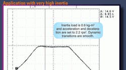
Example one:Application with very high inertia. Tuning with a 3-hp induction motor and ABM (Aries Blok Module) drive (as shown on the opposite, top plot) achieves a target dynamic transition and steady-state performance. Inertia load is 0.6 kg-m2 and acceleration and deceleration are both set to 2.2 rps2. Target speed is 15 rps.
Example two:Application requiring very high steady-state speed accuracy. After tuning, steady speed is accurate (as shown on the opposite, bottom plot.)
