Don’t Stress Out: How to Pick the Best Tool for Strain Measurements
Strain measurement is imperative during prototype design and testing. Measuring strain ensures that materials perform as they should and that equipment is safe, functional, and durable. The resistive strain gauge (RSG) has been the benchmark for measuring structural deformation for over eight decades, but today there are many technologies available to test and monitor stress and strain. Below, we discuss the use cases of strain measurement technologies in the aerospace and energy fields. This comparison will highlight the unique capabilities of each strain measurement device and determine the best technologies for strain measurement in each use case.
Strain Measurement in the Aerospace Industry
Stress and strain are the variables that determine the structural longevity and operational safety and efficiency of any aircraft. By testing, monitoring, and analyzing the integrity of an aircraft’s components, engineers can prolong a vehicle’s lifecycle and enhance in-flight efficiencies.
Wing load testing
During a wing load test, engineers depend on strain measurements to determine the structure’s performance and limitations under the lifting forces seen during flight. Two of the most effective methods of wing load testing are fiber optic sensing (FOS) and the resistive strain gauge (RSG). While both technologies are comparably accurate, each possesses its own unique merits.
NASA, to test the wing load distribution and wing deflection of the Global Observer aircraft in NASA Armstrong’s Flight Laboratory, has used FOS. The benefits of a FOS installation for this type of application are numerous. For instance, FOS technology provides strain measurement using thousands of spatially continuous sensors. This ensures maximum coverage from a single lightweight optical fiber. As FOS is immune to electromagnetic interference (EMI), radio frequency interference (RFI), or other electrical influences, these systems are ideal for use in hazardous environments and rugged applications, such as flight. FOS can be significantly less cumbersome to install than other sensing technologies. However, while the benefits of FOS are numerous, historically the initial cost of installing a system and lack of awareness has slowed mass market adoption. Moving forward, we anticipate reduction in the cost of FOS systems by 20% to 30% over the next five years, which will open up new opportunities in the automotive, medical, aerospace, and energy markets.
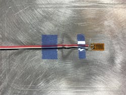
Strain gauges are still used today to verify the accuracy of analytical models that drive the design and manufacturing of structures and structural components. For example, Boeing has used strain gauges to test the durability of wings under load for some time. Although well understood and relatively inexpensive, strain gauges are difficult and time-consuming to install without the help of an expert; they can be affected by EMI and RFI, and are prone to hysteresis. A strain gauge only collects data from critical points and as a result does not provide a holistic picture of the load distributions.
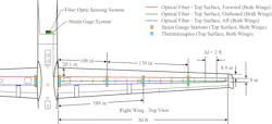
In 2009, NASA Armstrong, formerly known as NASA Dryden, conducted flight validation testing for a fiber optic shape and strain sensing system. Sensing fiber with approximately 3,000 fiber Bragg gratings (sensing points) was installed on the wings of NASA’s Ikhana UAV along with 16 strain gauges as indicated in the image below. The gauges were used to validate the strain data provided by the fiber Bragg gratings (FBGs). During flight, the FOS system was used to sense the shape and monitor the stress of the wings in real time. Strain data collected by the FOS was in agreement with the data provided by the strain gauges. A total of 18 flight tests adding up to 36 flight hours were conducted. During these flights, the tests consisted of the pilot pushed down on the stick quickly, then quickly pulled up for several cycles. The real time shape and strain data of the wings obtained by the FOS system was the first step toward controlling the shape of fixed wing aircraft. Strain gauges could not provide the density of information needed in order to monitor wing shape in real time, but were useful to confirm the validity of the strain data.
Fatigue testing
A material experiences fatigue after it is subjected to repeated loading and unloading. An estimated 90% of structural failures that occur in all industries are a result of fatigue. Many engineers use a strain-controlled testing method that uses cyclic loading to predict the life of an application under fluctuating loads.
The objective of a fatigue test is to determine the life and breaking point of a structure or component, i.e., the location of and number of cycles until failure when a material is subjected to a sequence of stresses. A number of methods are used to obtain stress and strain data, including strain gauges. The lifecycle of strain gauges themselves decreases dramatically as strains reach values of 2000-4000 µ-strain. This means that strain gauges are unable to accurately assess fatigue over certain parameters and over long periods of time.
FOS technology can provide engineers with accurate, real-time data on strain fields, load distributions, and residual strains resulting from overloading. Fiber optic sensors are resistant to temperatures ranging from cryogenic (< -150°C) to upwards of hundreds of degrees Celsius. This enables embedded fibers to be monitored during the high temperature cure phase of composite fabrication to determine the through-thickness residual stresses and strains. Because optical fiber is a ceramic and not a ductile material, its fatigue life far surpasses that of strain gauges and it does not exhibit hysteresis. For these reasons, continuous monitoring of composite structures can have far-reaching advancements. For example, commercial airlines will always know the state of fatigue damage on critical components, allowing them to fine-tune maintenance schedules and minimize aircraft downtime.
Strain Measurement in Energy
The wind industry is changing and renewable energy is gaining market momentum. Wind turbines can be found throughout the United States, positioned in locations where they can gather and convert as much energy as possible. For this reason, wind turbines must be durable. In addition, to improve efficiencies wind turbines are now being built taller and with longer blades. With bigger structures, loads become more significant, and maintenance becomes even more complex. The design of stronger, lightweight materials is imperative, but small inefficiencies during manufacturing or damage during operation can cause catastrophic operational failures.
More accurately detecting damage during runtime and at the finest resolution level offers benefits that translate into lower maintenance costs and the assurance of blade integrity. Blade geometry is carefully designed to maximize turbine efficiency, but the aerodynamic loads encountered during operation inevitably cause them to deflect, twist, and vibrate, leading to an altered aerodynamic response and decreased efficiency.
Strain gauges can be used to monitor wind turbine blade load during design validation. Some of the world’s largest turbine blade manufacturers rely on strain gauges to ensure optimal performance of rotor blades. Strain gauges can increase the reliability and function of wind energy technologies and thus reduce downtime. They provide critical measurements that help to maintain the operational integrity of wind turbines. For example, engineers use both strain gauges and FOS technology for chordwise bending tests on a full scale blade.
In addition to bending tests, FOS technology can take real-time measurements for operational data. By utilizing FOS technology to obtain real-time knowledge of turbine blade shape and load distributions, it is possible to compensate for performance changes. Control schemes utilizing this information may be developed to autonomously adjust the blades to decrease deflections, or to dampen out individual vibrational frequencies. Therefore, the blades would see less deviation from their nominal and most efficient shape. Data taken over longer periods of time would aid in the development of future designs, improving the future of wind turbines in the mix of renewable energy products.
Tensile Testing and Strain Measurement
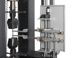
Tensile testing is a principal test, in which a material is subjected to tension until it reaches failure. This material test is used to select a material for an application, as well as predict the material’s behavior under different forces and strain parameters. This test measures properties for ultimate tensile strength, maximum elongation and reduction in area and is often used to ensure quality control of materials like metals and plastics. The strain measurements of a tensile test are often taken with an extensometer, but strain gauges can be used on a small test specimen or when Poisson's ratio is being measured.
The extensometer and strain gauge both provide reliable data; however, the extensometer offers several advantages over the strain gauge for tensile testing. Strain gauges with their accuracy, low cost, and ease of use are among the most common tools used in strain measurement and tensile testing. However, they can be difficult to apply and, as a result, can be misused and cause uncertainty in measurement. When tensile testing, strain gauge errors can be caused by temperature, misalignment, and the transverse sensitivity of the strain gauge. Additionally, bonding the strain gauge to the test piece can influence the outcome of the test.
The extensometer can be used up to the material breaking point without damage, even when testing specimens which are conducive to whiplash. Additionally, extensometers can more accurately determine strain when test samples undergo large deformations. The long gauge length of the extensometer also means that it can measure large applications. For example, the energy industry uses extensometer to measure displacements on high walls. Understanding displacement versus time helps engineers to determine when a wall failure is imminent. However, one large drawback of this technology is that it is dependent on the material that it measures. Additionally, extensometers can be more expensive to implement than strain gauges.
Smarter Products Means Smarter Data
Ever-increasing competition challenges companies to innovate, and do business faster and safer while keeping costs to a minimum. Utilizing the most appropriate technologies for your application can help improve prototype design and validation, helping businesses to create products more efficiently and safely. One way companies are able to overcome these challenges is by developing smart products. Global trends indicate that the demand for smart products, both industrial and consumer, is rapidly increasing. As the demand for these products increases, so does the necessity of not only more data, but actionable data. Over time, this data will help companies build safer solutions while pushing the limits of technology. As such, strain sensing solutions that provide spatially continuous strain information in real-time will be able to solve problems engineers face today and into the future.
About Michael Heflin
Michael Heflin is CEO of Sensuron, a global provider of fiber optic sensing systems whose mission is to solve problems on a global scale by utilizing light-based technologies that ensure equipment is functional, reliable and safe. Michael has been leading companies and inspiring teams for over 20 years. Specializing in identifying, growing, and increasing value in emerging technology markets, he has held executive roles at companies like Vantive, ADP, Fracta, Convergys, and Whisperwire. Before joining Sensuron, Michael guided four companies to lead their industry in sales, including two publically traded companies with valuations worth $2 billion. He has experience navigating domestic and international companies through successful acquisitions. Passionate about forming and counseling value-driven teams, he has a history of successfully guiding and inspiring teams worldwide.


