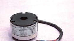
Optical encoders encourage efficiency
Brushless dc (BLDC) motors are used in countless applications. Many engineers today are looking to improve the performance of their BLDC-powered systems, and a new trend is emerging: An increasing number of BLDC motors are being built with more rotor pole pairs and stator phases. Motors with this construction offer high torque and stability. However, as we'll explore, getting the most from these new motors requires that they be used with optical encoders.
BLDC motor basics
Brushless dc motors consist of two major components — the rotor and stator. The rotor is covered with permanent-field magnets, while the stator consists of an armature winding on the soft metal, separated by 120 electrical degrees (°e). The system's drive provides phase-to-phase current flow through the stator winding, in turn generating a magnetic field to propel the rotor as magnetic fields of different phases are created. These phases are identified as U, V, and W.
For motors that directly drive loads, the torque/speed ratio must be flat — so torque must be stable, with minimum ripple. To this end, often the rotor's diameter is increased, more poles are added, and better magnetic materials are used. In fact, 8, 10, 20, or up to 30 pole pairs is becoming a common configuration for BLDC motors used for elevator traction and in CNC grinding, honing, and milling tools.
Elsewhere, in medium to heavy metal and wood processing machines, for example, torque density and load stiffness are also important. Here, where there is a need for both smoother torque and more of it, designs also use motors with more pole pairs. (Generally, the number of pole pairs increases proportionally with torque.) In addition, these motors typically include rare earth magnets (such as Nd-Fe-B) and large diameters to accommodate more pole pairs of shorter length. For example, an elevator drive motor might be one meter in diameter, with pole pairs only six inches long. A final approach to boosting torque density (and efficiency) is to increase both the number of pole pairs in the rotor and the stator's phase windings.
Incompatible: Hall sensors
For a conventional three-phase BLDC motor, three hall sensors generate a 120° angle. Typically, because hall sensors are open-collector devices, pull-up resistors are required for each sensor. These additional components, wiring, and joints are susceptible to corrosion and aren't always reliable. For this reason, some manufacturers reinforce their hall-sensor systems against harsh environments.
The hall sensors in BLDC motors act as a feedback system to the controller to track motor commutation. They do this by determining the present location of the rotor versus the stator windings. The information obtained is then used to energize the corresponding motor windings to make the motor turn to its commanded position. Hall sensors need to be physically placed 120° apart from each other, but sensor placement on PCBs (printed circuit boards) is often inaccurate. Such inaccuracies degrade BLDC motor performance, though filtering of sensor signals can mitigate this problem.
In contrast, some hall-sensor inaccuracies cannot be corrected: On motors that have an increased number of pole pairs, the electromagnetic compatibility (EMC) back current sensing of hall sensors is unreliable.
Compatible: Optical encoders
Optical encoders are a more accurate and reliable choice for motors with an increased number of commutation pole pairs. As we'll now explore, BLDC motor manufacturers and design engineers benefit, because these encoders can be built for any range of degrees, even to the slightest angles.
First things first. An optical encoder consists of three major elements:
-
The code wheel or scale is a patterned disk that regularly intercepts light transmissions as it spins.
-
The emitter consists of light-emitting diodes (LEDs) or infrared lights (IRs) aimed at a detector.
-
The detector consists of photosensitive elements — discrete photodiodes or more sophisticated phototransistor array integrated circuits. These translate the emitter's wheel-chopped light into electrical signals.
Continue to next page.
In short, an optical encoder works by transmitting light from the emitter through the patterned code wheel. The code wheel patterns act to block and then unblock this transmission, creating a series of shadows and light that falls onto the photodiode at intervals. This effect is detected by the photodiode with the encoder's commutation signal remaining highly accurate and reliable regardless of the number of pole phases.
Because an optical encoder is dependent on the code wheel, it can be further customized to accommodate higher pole-pair number requirements. (This is not possible with conventional hall sensors.) The minimum angle degree is 0.33° (for a maximum 180 pole-pairs) and is limited only by the photodetector design.
Note that having more pole pairs requires smaller steps from the motor to complete a full turn. For example, a BLDC motor with one pole pair generates six states, electronically separated at 60 mechanical degrees during one full rotor revolution. In contrast, a BLDC motor with two pole pairs generates 12 states, electronically separated at 30 mechanical degrees during one full rotor revolution. Increasing the number of pole pairs reduces signal ripple. At the same time, the reduction in signal ripple improves the power factor and smoothness of motor rotation. This in turn increases torque flatness.
Consider these parameters when choosing an encoder:
• Resolution (CPR — counts per revolution)
• Response frequency related to motor speed (Motor speed: Revolutions per minute = [Frequency (kHz) × 60]/CPR)
• Pole-pair number (different pole pairs will cause the motor to stall)
Newer six-channel commutation encoders include high-frequency responses to 250 Khz, a tapered shaft to handle axial vibration, and electronic circuitry for shield grounding.
Using a six-channel encoder incorporating a conventional ABI channel with a commutation UVW channel makes installation easier and, most importantly, boosts motor accuracy and stability.
For more information, visit Avago Technologies at www.avagotech.com.
