Motion control meets adaptive control
Proportional integral derivative (PID) control is the most common type of feedback control algorithm used in industry today. Because the PID algorithm can be tuned, it has been successfully used to control a wide range of processes that involve sensor feedback — from temperature chambers to motion systems. One drawback of PID control, however, is that tuning can be a time-consuming manual process and PID gains are optimized for the particular conditions that existed at the time of tuning. If conditions change, those PID tuning gains may no longer result in acceptable performance. Increases in friction due to normal wear and tear on mechanical assemblies, changes in temperature, or changes in payload mass may all necessitate retuning.
Engineers can overcome these traditional limitations of the PID algorithm by making the control system detect, respond, and adapt to changes. This approach can increase robustness, eliminate downtime for manual retuning, help the system automatically address wear over time, and even reduce energy consumption by optimizing the control performance for a given set of operating conditions.
First, specialized software identifies system changes by creating an updated model based on live measurement data. This is called “online system identification” because this task can be performed in real time while the control system is operating, and the process does not have to be interrupted. Next, a new set of PID gains is automatically selected by the software — based on the updated system model — to optimize performance for the new conditions.
Case in point: Linear motor adaptive PID control system
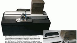
This approach was recently demonstrated on a linear motor control system using a reconfigurable I/O platform. Engineers at National Instruments set up an adaptive PID control system to automatically detect and retune itself for payloads from no weight to 120 lb. The engineers regularly added 20-lb weights to the linear motor carriage while it was in motion, requiring that the PID values be retuned.
In the system, a high-speed digital input module reads the linear encoder signals, which are converted to position and velocity feedback in the FPGA. Forward and reverse limit switches on the linear motor connect to a digital input module to provide a reference for the home position and to enable the enforcement of interlocks — which disables the drive if the linear motor travels outside the valid range of motion.
A 24-V digital output module sends drive control signals for enabling, disabling, and stopping motion. To increase performance, the PID control algorithm is executed in the FPGA at high speeds; the FPGA-based PID controller output is a torque command, which is transmitted to the servo drive using an analog output module.
Because the PID control algorithm comes from the FPGA and identification functions from the real-time processor, setup is simplified. After successful system identification and calculating new PID gains for the application, the real-time processor application sends the updated PID gains to the FPGA. This provides a clean architecture in which the FPGA is responsible for time-sensitive control tasks, while the processor executes the system identification functions at slower loop rates, sending updated PID gains only when valid identification results are available. More specifically, in the prototype by NI engineers, the system identification loop executes at a 5 Hz loop rate while the motion PID control loop in the FPGA executes at loop rates up to and beyond 20 kHz.
A recursive ARX model estimator function from the LabVIEW System Identification Toolkit estimates inertia. The torque command sent to the drive serves as the stimulus signal; velocity measured by the encoder is the response signal. With this, the ARX model estimator detects load changes. Because PID torque output is the stimulus signal, the model estimation is not affected by changing PID gains. In addition, using the recursive least squares (RLS) method allows the model to be updated dynamically while the system is running.
For more information, visit www.ni.com.
Adaptive motion control making strides
Javier Gutierrez, product manager for control, National Instruments, answers a few questions about the future of adaptive motion control.
MSD: Is adaptive motion control being used in real-world industrial applications?
JG: Motion control providers are always researching advanced control to improve performance and reliability while reducing costs and energy consumption. Online adaptive technology — where the model of the system under control is being calculated continuously over time — is not widely implemented yet. However, running one-time system identification techniques (the basis of adaptive technology) is finding use in high-end motion controllers to tune the correct gains.
MSD: For what types of applications is adaptive control best suited?
JG: Adaptive control performs better in systems where load changes over time. This can be applied to robotics, where the torque “seen” by the motor changes as kinematics change. Another example involves systems with a high wear rate, as the adaptive technology can compensate for it.
MSD: How far along is today's motion control technology with regard to fully embracing adaptive control?
JG: Adaptive control is still in its infancy in motion control systems due to the high processing power required to calculate the adaptation. It is currently used most in industries with lower loop rates, such as process control, where computing requirements are not as stringent.
