What’s the Difference Between Rigid-Coupling Types?
This file type includes high-resolution graphics and schematics when applicable.
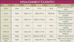
Couplings transfer power by connecting two shafts at the ends to transmit torque. While there are six degrees of freedom (DOF) to a shaft, coupling applications are only concerned with four—axial, angular, parallel, and torsional. Misalignment in any of these directions will cause balancing and vibration problems that can lead to shutdowns and damage. It will also greatly increase wear on multiple parts, such as the bearings. Making sure a motor is properly aligned can take experience and time, which may also not be ideal.
Thus, it’s important to have an understanding of the rigid couplings available for your design. Rigid couplings allow for no, or minimal, misalignments. Many types of rigid couplings are available, and they typically split into five general categories: setscrew, pins, keyed, splines and keyless.
Setscrews and Pins
For light-load applications a setscrew coupling can be quick and cost-effective. Products like Loctite can help prevent the setscrew from vibration-induced loosening. It’s suggested that setscrew couplings be used with only low loads and applications that will not see any shock loading.
Larger loads can be carried with a pin coupling. A hole is drilled through the hub and the shaft. Having the pin through the entire assembly doubles the shear area, since there are two shaft/hub interfaces. This is crucial in designs where the pin is to purposely fail in an overload or shock-load situation. A pin with a reduced diameter, which causes it to fail in order to protect more critical parts, is called a shear pin. The ability to carry a load can be calculated by taking the force divided by the area of the pin, on both interfaces, in shear.
A problem with pin couplings can be its tolerance fit—the potential of the pin being too tight or too loose in the hole. A pin that’s too loose can fall out and create backlash. If a pin is too tight, installation and removal can become difficult. A tapered pin can fix some of the problems, but often a spring pin is used. A spring pin is where the diameter is slightly smaller than the pin so that it forms a press fit into the assembly.
Another problem with all pin-type couplings is they require a hole that adds a stress concentration. To reduce the effects of a stress concentration, the pin can be laid parallel to the shaft and nest as a key between the interface of the shaft and hub.
Keys
A pin key will increase the cross-section in shear, making it able to handle larger loads. Woodruff keys are semicircular keys that are recommended (rather than pins) if the application has light loads and requires ease of assembly and disassembly. Another common key is a square or rectangle key.
Keys are simple ways to join the shaft to hubs and are relatively easy to design, considering their basic shear-force and compressive-force calculations. More complex designs often turn to spline couplings (depending on the design, they might also be called gear, sheave, or sprocket), because of their ability to handle great loads and reduce backlash. These couplings can greatly increase cost, though.
Splines
Spline couplings make a strong assembly between the shaft and hub. An SAE spline’s torque capacity is 1,000 psi bearing stress on the side of the spline. This information yields the equation:
T = 1000Nrh
where T= torque; N = the number of splines; r = radius; and h = depth of the spline.
A spline coupling is not designed to break to preserve components downstream from high or shock loads. Splines are essentially a set of axial keys, but have many benefits over keys. A spline transfers torque more uniformly, reducing force on the hub. Splines are precisely machined to resist movement, while keys will wear over time and can compress, causing movement and backlash in the assembly. Also, in the case of involute splines, the major diameter fit allows for accurate concentricity, and this form tends to center the shaft in the hub.
Keyless
Eliminating the key can make things easier for assembly and maintenance. Taper and screw, shrink and press fit, and clamp are some common types of keyless couplings.
Taper and screw is where the shaft and hub can be tapered, and is held in place by threading on the end of the shaft with a nut and washer to mate the components. Torque, load, and shock are limited with this coupling. Due to the machining involved it can be costly, too. Furthermore, if the nut is not tightened properly, it may not transfer torque, or it induces stress or fatigue in the shaft that causes it to break.
Taper and screw couplings are good for concentricity, and a key can be added to the taper and screw design to increase torque transmission. This type of coupling can be beneficial for applications with low loads and where the hub needs to be removed for maintenance.
Shrink and press fit are difficult to take on and off, but can form a tight keyless bond between the shaft and hub. These would not be good for applications that require the hub to be removed for maintenance. This is similar to the taper and screw, as they both rely on friction forces to hold the assembly tight. The more surface area and greater the force (without inducing a stress concentration), the more load the coupling will be able to handle.
Torque is important for many, if not all, industrial applications, but for keyless couplings it’s critical. In terms of clamp couplings, the fasteners that clamp the shaft and hub together must be torqued properly for two reasons: To gain the friction or crush necessary to transmit energy from the shaft to the hub; and not to be over-torqued, inducing stresses onto the coupling or other components.
Over-torquing can cause deformation in a thinner coupling, causing it to fail. In larger or more robust couplings, over-torquing fasteners will cause stress and fatigue, which may also lead to failure. Clamp couplings are easy for installation and maintenance, they’re cost-effective, and they don’t require machining into the hub or shaft. However, such couplings do require accurate precise alignment. Tapers and keys can help minimize concentricity or other DOF concerns, but such is not the case with clamp couplings.
With the potential of misalignment causing problems, flexible or compliant couplings can help minimize this concern. These types of couplings tend be much more expensive, but they’re viable considering the cost from wear on parts caused by misalignment. Also, some flexible couplings can be produced in large volumes to minimize this cost difference. Watch for “The Difference Between Flexible Couplings” next month.


