Interconnect Innovations Meet Demands of Shrinking Designs
This file type includes high-resolution graphics and schematics when applicable.
In today’s modern applications, interconnects are receiving more attention than ever as designs become smaller and more mobile. Simply put, interconnects are the travel paths of an integrated circuit, connecting elements of the circuit together and to other exterior components, such as batteries or electric switches. Metal layers of interconnects vary in numbers and sizes, depending on the complexity of the device. They can mate with other products via soldering or non-soldering joints.
We will review two types of interconnects: high-performance interconnects (HPIs) and battery interconnects. HPIs are used to send information through circuit boards. Battery interconnects transmit power to and from the circuit.
High-Performance Interconnects
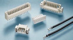
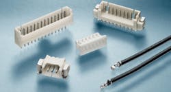
The high-performance interconnects from TE Connectivity can transmit low power and signals to devices, which allows them to operate certain features like a motor or light display. (Courtesy of TE Connectivity)
HPIs route signals or low power through a device. When using more than one printed circuit board (PCB), HPIs become an option to connect them. When deciding which interconnect to use, it is helpful to keep several design guidelines in mind. First, choose the correct gauge wire (AWG). The higher the AWG measurement number, the smaller the discrete wire. For example, a 32 AWG is smaller than a 22 AWG and will have less current-carrying capacity. HPIs can transfer signals that turn on low-powered devices like a fan, switch, display, or light.
Another key guideline is to know your operating conditions. This includes current, voltage, temperature, size of the PCB, height limitations, material restrictions, etc.
The HPIs developed by TE Connectivity come in a variety of settings. The vertical and horizontal interconnects have a centerline of 1.0 to 2.5 mm with max rated current amps from 1 to 3. Max rated voltage ranges from 50 to 250 offered in ac, dc, or ac/dc. Operating temperature ranges from –40 to 105°C. They are offered in either a through-hole (DIP) or surface-mount-termination configuration.
According to TE, its HPIs provide design flexibility and cost-effective wire-to-board installation to ensure proper compatibility of both the header and the housing; prevent stubbing contacts, and enable interchangeability with industry-standard designs. They will find homes in consumer, industrial, medical, and automotive applications.
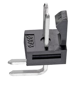
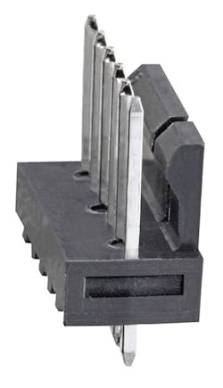
The KK 254 Right Angle and the Vertical (below right) interconnects from Molex provide a lead-free solder process that speeds up the installation process. (Courtesy of Molex LLC)
Soldering is one of the primary ways to install interconnects, oftentimes using lead. However, the reflow-process-compatible (RPC) interconnect solutions from Molex offer a lead-free solder process. With reflow soldering, solder paste is temporarily attached to the contact pads and subjected to heat, permanently connecting the joint.
Molex KK RPC products, which can withstand the lead-free process (temperatures up to 260°C), help maximize installation efficiency—applications can be designed to use the KK RPC with regular surface-mount components. Together they go through only one reflow process rather than sending them through an additional wave-soldering process after the surface-mount reflow process.
Specifically, KK 254 RPC interconnects are available in configurations up to 5.0 A, 250 V per circuit, and in 2.54-mm-pitch packages. The KK 396 RPC is well-suited for low- to mid-power, wire-to-board, and board-to-board applications. Operating temperature for brass versions is –40 to 80°C; for phosphor bronze, it ranges from –40 to 105°C. Contact resistance is 10 milliohms maximum, while insulation resistance is 1,000 megohms minimum.
Other connectors offer mating pieces that require no soldering at all. For example, interconnects from Autosplice are press-fit terminals and connectors.
Converting board connections to a lead-free process has been difficult. They have been particularly challenging for heavy copper PCBs, such as power interconnects. While manufacturers have made progress converting surface-mount-termination processes to lead-free, secondary soldering operations have always been problematic in achieving a high productivity and volume assembly rate. This problem is apparent in markets like the automotive industry, where large molded connectors are frequently used for power and control signals.
Autosplice’s Compliant technology allows for high-speed machine insertion of an individual interconnect, or multiple interconnects, with no need of soldering. The Compliant technology uses a special design for the insertion section of each pin, providing a robust and gas-tight interface with the plated through hole. The insertion section of the pin is larger than the diameter and deforms as it is being inserted, creating a strong friction-fit.
Besides a non-solder joint, the Compliant terminals come in handy for those power interconnects on heavy copper PCBs. The ability to insert the contacts directly onto the PCB without soldering can eliminate the need for separate molded connectors. This helps accommodate fine-pitch space constraints and reduces overall size and weight.
The Autosplice Compliant/Press-Fit interconnects and contacts are plated with tin or tin-lead over nickel. The forces required to insert the connectors is a maximum of 60 N for a 0.64-mm connector and 132 N for a 0.81-mm connector. Retention force is 47 N and 88 N for 0.64- and 0.81-mm connectors, respectively. The series has a current rating range from 7.5 to 25 A. They can operate in environments ranging from –40 to 125°C, and handle vibration and mechanical shocks of 1.8 G on a random axis. The interconnects can function for 40 cycles from –40 to 125°C at a relative humidity of 95%.
Battery Interconnects
As mobile equipment continues to shrink in size, available space for battery packs disappears as well. As a result, design requirements demand that they carry a balanced current, provide higher amps, and support faster charging times.
Battery interconnects are available in coplanar, parallel, or perpendicular configurations. It is important to note the lengths of the pins and sockets to ensure they do not exceed their mating counterpart on a PCB. The voltage key is indicated on the PCB.
For coplanar configurations, the PCBs are on the same plane when both plug and receptacle are mated. When mated on a parallel configuration, the PCBs do not intersect. On perpendicular configurations, PCBs meet at a right angle when the plug and receptacle are mated.
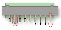
In this eight-position connector, three pins are reserved to flow power out of the system to the battery while three other pins flow power from the battery pack into the system. The large pin circled on the right is reserved for grounding. The center pin is designated for signal requirements, and the circled pin on the left is a keying feature for mating components. Photo (Courtesy of TE Connectivity)
The following terminology helps define the power design requirements for battery interconnects:
• Current-carrying capacity: The maximum current an insulated conductor is capable of carrying without exceeding the safety of the interconnect (i.e., insulation or jacket temperature).
• T-Rise: The change in temperature in a terminal from a no-load condition to a full-current load.
• De-rating: Specified reduction in output power required for operation during high temperature levels. This feature is necessary when loading multiple contacts between a system and battery pack.
• Keying feature: Mechanical arrangement that allows connectors of the same size and type to mate.
• Grounding pin: Typically the longest pin used as a conductor to provide a return path for the current from a device to ground.
To calculate the carrying capacities of a battery-pack interconnect, one cannot multiply the maximum current per pin by the number of contacts. The maximum current typically listed for a battery pack is for a single contact. When many contacts are used to transfer power, it decreases the maximum current-carrying capacity of the individual contacts. Assume one contact can carry 7 A. This is the total current for both power in and out. To calculate the one-way maximum current, the total current is divided by two.
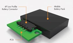
The TE Connectivity 5A interconnectâs low mounting profile helps reduce the space needed for installation. (Courtesy of TE Connectivity)
The battery interconnects from TE Connectivity offer high-performing and multi-directional performance—a key feature for devices such as PCs or smartphones. Their operating temperature range is –30 to +85°C. The contacts are comprised of brass or copper with duplex plated tin, gold, or tin or gold lead solder tails and nickel on the mating area. The materials ensure the life longevity of the product and provide high cycle mating/unmating of interconnects. The housings consist of high-temperature UL 94V-0-rated thermoplastic to protect from overheating.
The newest battery connector from TE is the 5A Low Profile battery connector. Its one-piece contact design supports fast charging speeds. The 5-A current rating and 30-V dc rating help support the charging speeds. This is useful for many mobile devices, such as portable keyboards, tablet PCs, mobile phones, and navigation systems. Its dimensions also help reduce the space requirements that are needed for small and mobile devices. The base materials are copper alloy for the contacts with gold over nickel for the contact mating area. Four point positional contacts allow for development of different product configurations.
