Industrial Digital Inputs: They’re Not Quite as Simple as Counting from 0 to 1
How hard is it to keep track of a binary electronic system? It can only be in one of two states: on or off, open or closed, 0 or 1. While that may be correct, let’s suppose that there is no strict definition of what voltage levels constitute a “0” or a “1.” Let’s now also suppose that the voltage levels for a 0 or 1 can change during transmission. This could be for several reasons—noise, line impedance, electrostatic discharge (ESD), power surges, or perhaps even a combination of them all.
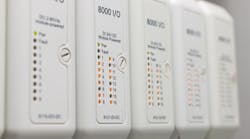
How can you be certain that what started out as a 0 is still a 0 and that what started out as a 1 is still a 1? Imagine also trying to keep track of dozens of these signals simultaneously and quickly. What may initially have appeared to be a relatively trivial task has taken on a whole new level of complexity. Welcome to the world of the digital input (DI), a subset of the IO module (Fig. 1) that sits between an industrial sensor and a PLC.
In this design solution, we will review the many (sometimes contradictory) requirements for a successful DI circuit and propose a solution that rises to the challenge of operating successfully in a modern industrial environment.
What is a DI?
The purpose of a DI circuit is to receive a binary signal transmitted by an industrial sensor on a factory floor and “condition” it. This is so that it can be safely and reliably interpreted by the PLC responsible for monitoring the state of that sensor. Examples of such binary signals include pushbutton switches that determine if a piece of equipment has been switched on or off and transducers that determine if a pressure or temperature threshold has been exceeded. Therein lies a clue to the first challenge for the DI circuit: There is no single definition of what a signal coming from an industrial sensor/transducer should look like.
Flexibility and Configurability
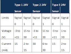
Presently, there are three different types of 24V DC current-sinking industrial sensors recognized within the industrial standard IEC61131-2.
- Type 1: Electromechanical
- Type 2: Discrete high-current semiconductor
- Type 3: Reduced power consumption semiconductor (current ≤ 2mA)
The differences are primarily related to the voltage and currents they produce. The “state-of-the-art” integrated circuit (IC) sensor is Type 3, although there are many legacy Type 1 and Type 2 sensors successfully operating on factory floors. However, Type 1 and Type 2 sensors need to sink much more current than Type 3 sensors. Therefore, even though the current produced by a Type 3 sensor is much lower (defined in the IEC standard to be as close to 2 mA as possible), a flexible DI circuit must be configurable so that it can sink current levels from Type 1 and Type 2 sensors, if required. This means the DI circuit must handle a wide range of different input voltages (−3 V to +30 V) and currents (2 mA to 30 mA), as shown in the table.
Source: maximintegrated.com/design-solutions
Early DI circuits were built using discrete components (Fig. 2). Even with a custom current-limiting circuit, this type of DI circuit would consume over 5mA of current. Clearly, this made it unsuitable for use as a Type 3 DI (consuming over twice the required current).
Discrete DI with current limiting.
Integration and Scalability
With increasing decentralization and miniaturization of industrial process control technology, it has become necessary to pack as many channels as possible into IO modules to save space in the control racks. This drive toward miniaturization has also impacted the DI.
Today, typical IO modules contain combinations of 8, 16, 32, or even 64 separate input and output channels within a single enclosure. To facilitate this level of integration, it was necessary to both reduce the physical size and current consumption (and associated heat dissipation) of DI circuits. This necessitated a move away from large, power-hungry discrete circuits. Contemporary multi-channel DI circuits are built using IC technology, making it possible to attain the lower current consumption required for a Type 3 DI within a much smaller form factor.
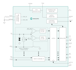
An example of this is the octal DI IC (shown in Fig. 3), which operates as a Type 1, Type 2, or Type 3 DI. When used as a Type 3 DI, it has programmable current from 0.5 mA to 3.4 mA, per channel.
To reduce the number of channels required to interface with the PLC, this device translates the eight DI 24 V current-sinking channels into a 3.3 V to 5 V logic serial peripheral interface (SPI)-compatible output. For systems with more than eight sensor inputs, multiple devices can be daisy-chained together to allow access to all data inputs through a single serial port, providing an even higher level of integration.
MAX22190 octal DI.
Robustness and Integrity
A multi-channel DI IC must be robust enough to operate in industrial environments—which are high voltage, noisy, and harsh—so that the measured sensor signal can be transmitted to the PLC with a high degree of integrity. This requires a degree of fault tolerance on both the inputs (field side) and outputs of the IC.
In demanding factory conditions, voltage transients are common, such as when motor drives switch on and off. These can affect sensor readings. To prevent this, each DI channel should have a debounce filter with a programmable delay that can remove transient under/over voltages from the sensor signal. Similarly, other ideal field-side diagnostics include the ability to detect a wire-break from the sensor, an overtemperature condition, or a voltage supply fault to the part itself.
On the output side, with multiple input channels being transmitted on a single SPI, the ability to error-check (e.g., cyclic redundancy check) the serial bit stream ensures that all sensor readings are trustworthy and that no error has occurred during transmission to the PLC. These diagnostics are present on the previously mentioned octal DI IC, which operates directly from field-side voltages (up to 65 V) and includes robust protection up to 1 kV
Safety and Reliability
Field-side voltages, which can go up to 65 V, are much higher than the logic-level voltages used by PLCs (typically 3.3 V to 5)V. As such, if the PLC were to accidentally encounter the higher field-side voltages, it could be damaged or destroyed. Even worse, such a scenario could cause a safety hazard to the equipment user. To prevent this from happening, it is necessary to introduce galvanic isolation between the field side and the logic side. The isolator chosen must operate at the transmission speed of the SPI interface of the digital Input IC (in this case 10 Mbps).
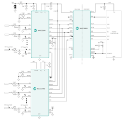
A composite DI and isolator solution illustrated in Fig. 4 withstands ESD voltages up to 3.75kVRMS. This device does not add significantly to the overall current consumption of the solution as it only consumes 3.4mA (at 500kHz).
Two daisy-chained isolated octal digital inputs with isolation. (Source: maximintegrated.com/design-solutions)
Conclusion
In this design solution, we reviewed the key design requirements for the DI component of an industrial IO module. Having considered the limitations of older discrete DI implementations, we conclude that a composite solution using a multi-channel DI and an isolation IC offers the best guarantee of the integration, scalability, robustness, integrity, safety, and reliability needed for detecting sensor signals in a modern industrial environment. Apart from industrial automation and motor control, the solution presented here is also suitable for building automation and robotics applications.
Michael Jackson has over 20 years’ professional experience as an analog IC design engineer and holds the position of senior technical writer at Maxim Integrated. Sean Long is director, applications for the Industrial and Healthcare Business Unit at Maxim Integrated.


