An electronic revolution in the construction and agriculture vehicle market is well underway. It is analogous to the electronics revolution that swept over the automotive market in the last few decades and which continues to accelerate with the roll-out of Advanced Driver Assistance Systems (ADAS) and fully autonomous vehicles.
A passenger vehicle may have more than 20 microprocessors today. The microprocessors are busily working, doing complex things that may include:
- Telling the vehicle where it is and where to turn;
- Making it more fuel-efficient;
- Keeping you safe with electronic stability control;
- Deploying an airbag in the event of a crash;
- Keeping the window from pinching your fingers; and
- Opening the rear hatch as you pass your foot underneath the rear bumper.
All of these processors are hungry for information with which to make decisions. Sensors provide this information, and they are more numerous than the processors. The number of sensors and processors in any given vehicle will increase as vehicles add more features and become more autonomous.
Much like we see Advanced Driver Assistance systems being deployed in today’s passenger vehicles, similar systems are being deployed in the construction and agriculture vehicles.
The past five years saw the introduction of nearly autonomous agriculture tractors designed to maximize efficiency in planting, fertilizing, and harvesting crops. Systems that are currently deployed and working virtually autonomously eliminate overlap during planting and fertilizing—making farming more efficient. These next generation tractors use information from GPS satellites and on-board inertial sensors to precisely know the location (around 3 to 10 cm) of where they are planting a seed or putting down fertilizer. In construction, we see the introduction of fully autonomous haulers deployed in mining operations and systems added to excavators and loaders for precision excavation.
The challenges for autonomous construction and agriculture equipment are somewhat different than for passenger vehicles. In a field, there are no lane markers, signs, or sidewalks for a vision or LiDAR system to utilize to help keep the vehicle on a desired path. Additionally, cars do not have appendages like booms and buckets—cars cannot swivel on their base like an excavator. Systems for the construction and agriculture vehicle need to know precisely where they are, their orientation, and where their appendages are.
Let’s take a look at a real-world construction system and the sensors being used in a precision excavation application.
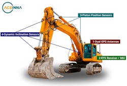
Precision excavation is just what the name implies; it prepares a site for construction. The project could be an office building, bridge, tunnel, dam, or other structure. Preparing a site with an precise excavator means less time wasted working on the site, with smaller equipment bringing the site into the tolerances needed in the design (Fig. 1).
1. Heavy construction equipment like excavators often use a variety of sensors to ensure highly accurate operation. These include GPS receivers and antenna, inclination sensors, and IMU and position sensors.
First the vehicle needs to know where it is and its orientation. The primary location system used is Global Navigation Satellite System (GNSS) -based and is often mounted around the cab.
There are a variety of GNSS systems deployed and operational. In North America, the one we are most familiar is GPS. However, regular GPS is only accurate to about 6-10 meters, which is not adequate for this application; regular GPS cannot provide heading information unless the vehicle is in motion. These limitations are addressed using either Differential GPS (DGPS) or Real Time Kinematic (RTK) GPS.
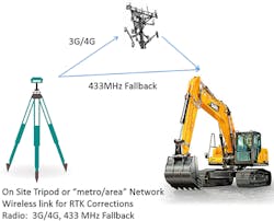
DGPS and RTK both require a local stationary GPS receiver for which its location is precisely known. The stationary receiver compares its known location to its location as calculated by the GPS receiver (Fig. 2). From this information it can generate corrections which it transmits to the other mobile GPS receivers located on the vehicle.
2. GPS information transmitted to a stationary and a mobile GPS receiver enables an excavator to accurately locate itself.
The mobile receivers then apply the same corrections to their location calculations, resulting in a much more accurate solution (around 10 to 30 cm vs. about 6 to 10 m). RTK improves the accuracy even further by using information from the GPS transmission, and the GPS carrier for a better time accuracy—and therefore, position accuracy.
The heading limitation of GPS is overcome by using two GPS receivers on the excavator with the antennas separated in space by some reasonable distance (1 to 2 m), as shown in Fig. 1 (1- Dual GPS Antennae). The absolute position of receiver 1 to receiver 2 antennae is used to calculate the absolute heading.
To supplement GPS and RTK, an Inertial Measurement Unit (IMU) is installed in the vehicle usually centrally located to the vehicle. (See 2 RTK Receiver/IMU in Fig. 1). An inertial measurement unit measures 3 dimensions of linear acceleration (3D Accelerometer) and 3 dimensions of rotational rate (3D Gyro), and sometimes also a 3D magnetic field.
Magnetic field information can calculate heading like a compass does, but in many instances, it is not very useful in construction vehicles because there is so much iron distorting the local magnetic field.
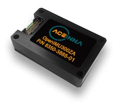
3. The ACEINNA OpenIMU300 MEMS-based inertial measurement unit provides real-time information as to what is happening on the machine chassis and its attitude (pitch and roll).
The IMU supplements the DGPS/RTK information by providing real time information as to what is happening on the chassis and its attitude (pitch and roll). From the IMU, real time solutions of attitude and velocity are performed and combined with the DGPS/RTK information to determine precise location, attitude, and motion of the excavator dynamically in real time. With the excavator chassis location and motion known, the location and orientation of the bucket (business end of the excavator) needs to be determined.
In Fig. 1, we show two possible solutions for determining the bucket location. (label 3 piston position sensors and 4 dynamic inclination sensors). In both cases geometry calculates the position and orientation of the bucket. Sensors on the hydraulic pistons can tell how far they are extended or retracted. In addition to, or instead of the piston sensors, dynamic Inclination sensors can be mounted on the excavator’s boom and bucket to provide attitude relative to the earth’s gravity vector.
Similar to IMUs, dynamic inclination sensors have 3D accelerometers and 3D gyros. However, they also have advanced algorithms running inside to calculate orientation and provide pitch, roll, 3D rate, and 3D acceleration on the CAN bus. This attitude information, the known geometry of the excavator, and previously calculated heading, attitude, and motion of the chassis are combined to calculate the exact position, attitude, and motion of the bucket including its teeth.
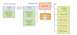
4. System architecture; A lot of working parts combine to provide the highest levels of accuracy
These sensors (DGPS/RTK, chassis IMU, boom, stick, and bucket dynamic inclination sensors), along with the information they provide, allow for complete and accurate control of the excavation process. The last step is to marry the capability with electronic site survey and site preparation plans. Figure 4 shows how the pieces of the solution interact with each other.
The stationary GPS transmits the GPS correction to the RTK system on the vehicle via a 3G/4G or radio link. The vehicle RTK system uses the information to correct its position calculations. The main CPU then calculates the positon of the bucket using the corrected RTK position, chassis IMU (often embedded in the RTK system), boom, stick, and bucket sensors, along with the known geometry of the excavator. It compares the site survey and the site plan loaded into its memory. It can now control the movement of the vehicle and the excavation process thru the hydraulic control to remove the material in the site survey which is not in the site plan.
Drones can survey sites and develop the information to be fed to the excavator. The drones are also equipped with similar sensors, including GPS and IMUs, as well as others like LiDAR, radar, and vision systems for surveying the land below. It is now possible to accurately survey a site in a day and have all the information available electronically.
Fully autonomous construction equipment and vehicles are here already and doing work every day. Check out Volvo’s autonomous electric dump truck, filmed at the last Conexpo, and Built Robotics’ automated loader.
Komatsu is offering an intelligent family of products. Caterpillar has autonomous dumps as part of it Cat Minestar products. Some of this equipment shows the promise of being able to work 24/7, just needing to stop occasionally for refueling and maintenance.
The electronic revolution is well under way in the construction and agriculture vehicle market, fed by GPS and MEMS-based sensors. Autonomous solutions are delivering higher efficiency and safer work sites. We expect this trend to rapidly accelerate as these technologies become more accepted throughout the construction industry, with inertial sensors and RTK GPS enabling greater autonomy.
James Fennelly is product marketing manager - Tilt and Inclination Sensing for C. He has been working for the past 10 years with MEMS inertial sensors, including component level acceleration sensors and system level products.
