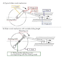
A slider-crank mechanism is a typical design which converts rotary motion into linear motion. It is achieved by connecting a slider and a crank with a rod. Figure A depicts a mechanism utilized as a system that converts the reciprocating linear motion of an automobile engine into rotary motion.
The second figure, B, is an example of the mechanism that has the same functions as the slider-crank in the first figure A in addition to the sliding stroke adjustment feature for the slider. To add this feature, the sliding stroke adjusting screw is placed on top of the rotation shaft center of the rotation disk. The sliding stroke can be adjusted by the adjusting nut located on one end of the sliding stroke adjusting screw.
A and B. The two mechanisms above are examples of slider-crank mechanisms.
In addition, if high-speed rotation or operation for long hours is required, it is necessary to consider design items related to the reliability matters described here.
- Rotation balance of rotating body (the entire structures on the disk)
- Strength of rotating shaft
- Prevention of adjusting nut-loosening (e.g., double-nut system)
- Selection of wear-resistant parts for the area subject to wear
Figure C below illustrates the mechanism with exchangeable rod/slider parts. A U-shaped hook is installed so that the tip of the rod can be easily connected to the hinge pin at the hinged end of the crank.
C. Example of a slider-crank mechanism with exchangeable rod/slider parts.
Application Examples
For simple automation devices or fixtures made compatible with multiple models by connecting a processing unit to the slider unit, exchanging the slider unit after preparing a processing unit off-line can minimize the time required for mode switching.
- The drive mechanism of the squeegee unit for a simple screen printing machine: When materials are replaced owing to the pot life, or when printing materials are replaced, it is possible to switch models quickly if you remove the slider parts with the squeegee integrated and exchange it with the slider parts with its squeegee position adjusted offline.
- Simple press mechanism with multi-model compatibility.
Application Challenges
Because of this simple coupling method, where only a U-shaped hook is placed over the rotating crank, this mechanism is not compatible with the following types of motion:
- A high-speed rotating crank: The self-weight of the rod may not be sufficient to follow the motion.
- A large rotating radius: Motion from the crankshaft to the U-shaped hook will not be transmitted effectively in some areas.
- Motion involving unstable speed or oscillation: The U-shaped hook may fall off.
How to Use a Slider-Crank Mechanism
Figure D shows an automation clever mechanism that converts crank rotation into linear motion and makes the linear motion stroke twice that of the original one.
D. The stroke-doubling mechanism.
In this structure, the slider used in the standard slider crank mechanism a toothed gear. In addition, the slider guide is separated into a fixed rack and a movable rack. The crank motion on the driving shaft is transmitted to the toothed gear. Then, the stroke of rolling motion (L) over the fixed rack increases by 100% (2L) when it reaches the gear top. This stroke (2L) acts on the movable rack installed on the gear top.
More Application Examples
The structure tends to be longer than originally intended if a pneumatic cylinder and a linear guide are used, or if a structure where ball screws are used for connecting a motor is adopted. This automation clever mechanism is an effective solution for making the fixture short and compact:
- Oscillating motion of a processing machine
- Reciprocating linear motion mechanism for one-piece flow production fixture
(printing, wiping, and pressuring) - Inspection jigs
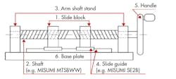
Rotary motion can be converted into linear motion by using a screw. This volume introduces an automation clever mechanism (Fig. E) that allows control of linear motion in various ways by adopting different types of screw structures. “Threaded” and “tapped” screws are used as a cam.
E. Linear motion conversion mechanism involving movements in two directions.
If the handle installed on the right edge is rotated, it causes a linear motion of the slide block placed on the two tapped screws that are assembled to the opposing two screws. This structure can also be applied for a double-speed mechanism, where single rotation of the handle is transformed into a movement of twice the pitch of the rotation.
Even More Application Examples
- Electric terminal positioning or scanning movement for inspection equipment
- Adjustment mechanism for edge positioning of jigs compatible with various products.
- Double-speed mechanism
Cams
A cam is the typical mechanical component used in the rotary-linear motion conversion mechanism. Cams are the excellent choice because of the following characteristics:
- Motion characteristics such as speed, acceleration, and forces can be freely controlled by the output end to which the cam motion is transmitted
- When combined with the link mechanism, incorporating a cam into the structure allows you to design a compact, lightweight, yet highly rigid mechanism in a simple structure
- Cams can shorten the overall cycle time as they can overlap and control multiple movements
- Highly reliable
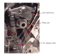
Based on these characteristics, cams are adopted in various applications, including the terminal press-fitting mechanism of a high-speed terminal press-fitting machine, as well as the high-speed and complex timing control of an air release valve for an automobile engine (see photo). In the photo below, displacement of the plate cam is enlarged by the link mechanism. To ensure the high-speed responses, springs to prevent jumping have been installed.
Control cam for air release valve in automobile engine.
A cam introduced here as the basics of automation clever mechanisms works as a supportive element that allows for quick attachment/detachment of fixtures by transforming the linear motion displacement into forces, rather than converting rotary motion into linear motion, which was explained earlier as a superior characteristic of cams used in motion control.
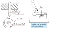
Rotary-linear motion conversion mechanism using a cam.
In Fig. F, the rotary-linear motion conversion mechanism using a typical plate cam and a reciprocating follower is shown left and the one-touch clamp mechanism next to it.
The mechanisms above are examples of how you translate rotary motion into linear motion.
Rotary to linear motion conversion can be configured with a variety of components and achieved with varying degrees of accuracy and strength. Be sure to check out cam units, gears, gear racks, and other rotary and linear motion components on MISUMI USA’s website.


