Download this article as a .PDF
Hoses and couplings are critical parts of every hydraulic system. They transfer hydraulic fluid from the pump to machine components such as valves, motors, and actuators which use the fluid pressure and flow to create the machine motion and force needed to do work. The importance of selecting or replacing hydraulic hoses and couplings often gets overlooked…until something goes wrong.
Engineers must consider several factors before choosing hydraulic hose assemblies.
Hose and Coupling Basics
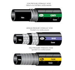
Most hoses have three functional layers—the tube, reinforcements, and the cover—assembled in a flexible “laminate design” or “composite structure.” Being flexible lets the hose move, flex, easily route through bulkheads, dampen pressures surges, and withstand vibration (as compared to rigid pipe or tubing).
Hoses are built and tested according to industry specifications such as SAE and EN. Engineers should be familiar with specifications related to equipment the hoses they design will go on. They provide guidelines for dimensions, material properties, and minimum performance characteristics for major types of hose and couplings.
The tube conveys the fluid and is commonly made of rubber compounds and plastic. It’s critical that the tube resist fluids it carries and is exposed to; permeation by chemicals; and both high and low temperatures.
Reinforcements include natural and synthetic fibers, wires and cables, and monofilament. They help hoses withstand internal and external pressures.
Covers, which are commonly made of rubber, plastics, and textiles, protect reinforcements from the environment. They resist abrasion, chemicals, weathering, and ozone.
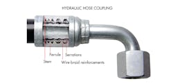
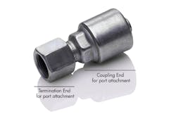
Couplings make leak-free connections to the hose (coupling end) and attach the hose to different components in the hydraulic system (termination end). Most couplings have two parts, a stem and ferrule. The stem conveys the fluid, attaches to the hose, and provides a seal between the stem and hose. The ferrule attaches to the reinforcements and serves as a “weather seal” to protect the hose and coupling from the environment. Both are typically made of carbon or stainless steel, and are sometimes plated or coated to improve chemical or corrosion resistance.
Couplings on the market include one- and two-piece designs. In the one-piece versions, the stem and ferrule are pre-attached or staked together as one part. Two-piece designs have separate stems and ferrules which are joined by crimping.
The termination end forms a leak-free connection between the hose and a port, adapter, or another hose. There are many different types of end connections specified by industry standards (such as SAE J516). Knowing how they fit together is key to selecting the best termination for an application.
Defining Requirements
There are several hydraulic-system characteristics that help engineers design hose and couplings for maximize service life: size, temperature, application, material, and pressure. Here’s a look at each.
Size: A hose’s two critical dimensions are inside diameter (ID) and overall length (OAL). The ID must be sized to keep fluid velocities within recommended ranges. If the ID is too large or too small, it can change fluid flow and hurt machine performance by causing erosion, excessive pressure drop and power loss, too much turbulence (heat generation), pump cavitation, or noise.
The OAL must be sized to provide proper routing. Too short, and it puts excessive stress on the hose and coupling and prevents them from bending and stretching due to pressure impulses. If the hoses are too long, they can rub against each other or nearby components, or get caught on something.
For most hydraulic applications, hose sizes are listed as a -4, -6, -8, etc. The number is the hose’s ID in sixteenths of an inch. For example, a -4 hose (pronounced “dash four”) has an inside diameter of 4/16” or ¼”. 100R5 and 100R14 hoses are exceptions. They are sized according to OD (similar to rigid pipe) and have IDs slightly smaller than their dash size.
When replacing a hose, you can determine the ID by checking the label. If it has been painted over or worn off, do not use the hose OD to identify the hose’s ID. Hose ODs vary according to construction and manufacturer and have no direct correlation to IDs. A better option is to cut the hose and measure the inside diameter. Remember to record the overall length and coupling orientation before cutting the hose.
When designing a hydraulic system and specifying new hoses, use a nomographic chart or fluid flow calculator to determine the proper hose size.
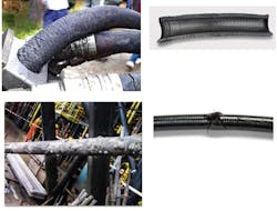
Temperature: Temperatures too high or low can degrade hydraulic system performance and hose service life. High temperatures stem from excessive internal or external heat. Internal heat usually comes from system components and is transferred to the hose through the fluid. External heat can result from routing hose too close to an engine, past a manifold, or close to a heat exchanger or other hot spot. Excessive heat cracks and dries out hose covers. There will usually be tube cracks on the inside as well, but they are only found after sectioning the failed hose. Cracked hoses no longer protect reinforcements and should be replaced.
Damage from cold temperatures usually happens as hoses flex or bend when below their negative temperature ratings. This typically occurs when moving machinery before the hydraulic fluid warms up, or else removing and straightening coiled hose that was kept in cold storage.
Hoses’ temperature ratings, both minimum and maximum, are usually listed in agency specifications, product catalogs, or technical pages. Most ratings are for normal service conditions, but special ratings are sometimes listed for intermittent service. Plastic hose pressure ratings are often reduced by a temperature factor.
It does not take much extra heat to shorten a hose’s service life. A good rule of thumb says that for every 18°F over a hose’s maximum temperature rating, the hose’s life is shortened by 50%.
The preferred option for managing temperatures is to ensure the hydraulics’ heat and external heat sources stay within acceptable ranges. The next best option is to select hose and couplings that withstand extreme temperatures. Be sure to choose hose with an upper limit well above the machine’s operating temperature. Another way to protect hoses from heat is installing insulating sleeves over the assembly.
Application: Engineers need to document anything special the machine they are designing is expected to do, including safety and environmental risks, and extreme conditions the hose will be expected to handle.
Does the machine need to meet any agency, industry, or customer specifications? How long should the hose remain in service? Are there cleanliness requirements? (75% of all hydraulic failures result from contaminated fluid. If not controlled, particles too small to be seen can reduce hydraulic system efficiency by 20%.)
If replacement hoses are being made, ask some questions rather than just duplicating the originals. How did the original hose fail? Does it show signs of cover abrasion or temperature cracks? Does the machine generate pressure surges, or is it more of a static application? Make sure to find a replacement hose that best matches the application requirements, not just the original part.
It’s also a good idea to brush-up on new hose technologies. Over the past several years, some manufacturers have developed hoses and couplings that far exceed the performance and construction capabilities of SAE specifications. These include higher pressure and temperature capabilities and greater flexibility, along with the ability to bend twice as tightly as standard hoses.
Hoses that meet or exceed SAE performance specs, but are smaller than standard hose, can be good choices. Recent material advances give these “hybrid hoses” thinner tubes and covers, smaller-diameter wire reinforcements, and more aggressive braid-reinforcement angles. These result in hoses with the same ID but smaller ODs. This new generation of hoses is more flexible and 10 to 15% lighter than earlier-generations.
Today, leading manufacturers offer spiral-wire and wire-braid hoses with minimum bend radii up to one-third less than SAE specifications, reducing the overall length of curved assemblies and cutting costs by as much as 60%.
Compact and flexible hoses are easier to install and route in tight applications, require fewer bent-tube fittings, reduce inventory, and extend life in bending, flexing applications.
Material: Most hydraulic fluids are petroleum-based. Others are water-based, water glycol, or synthetic-based (such as phosphate esters). In the past, hydraulic-fluid leaks have contaminated soil and fouled water supplies. As a result, the industry is moving to more environmentally friendly fluids.
“Green” fluids are typically synthetic (primarily ester-based) or vegetable-based. Vegetable oils are gaining popularity because they cost less and are more biodegradable than synthetics. They also have excellent lubricity and a high viscosity index. The downside is their limited temperature range and rapid oxidation at higher temperatures.
Biodegradable fluids might be great for the environment, but they are tough on hoses. They permeate through standard hose tubes, causing cover blisters and sweating moisture on hose covers, which leads to premature hose issues and creates a mess of oil and dirt.
Most manufacturers use high-grade nitrile tubes for environmentally safe hydraulic fluids. Nitriles are tough enough to handle aggressive biodegradable fluids such as synthetic esters, polyglycols, and vegetable oils at operating temperatures up to 250°F. Nitrile materials also allow less permeation than neoprene when used with petroleum-based oils. (Permeation, or effusion, is fluid loss through the tube and hose.)
Because permeation may expose the entire hose assembly to fluid, check the fluid’s compatibility not only with the tube, but with the reinforcements, cover, fittings, and seals. The same holds for assemblies that handle special oils or chemicals.
The most critical hose and coupling material consideration is chemical resistance, so confirm what fluids will run through the hose. Which fluids or gases might permeate the tube and potentially weaken the reinforcement layers? And what materials will touch the hose cover in normal service or cleaning?
What corrosive chemicals will touch the coupling bore, ferrule, and termination? Does the termination use O-rings or elastomeric seals? Are internal system fluids compatible with seal components?
Will these chemicals be in constant or intermittent contact with the hose and couplings? What are the chemical concentrations and are their properties affected by temperature?
There are several resources that provide details on materials’ chemical resistance. The first, a chemical resistance guide, describes the general properties of tube and cover compounds. For example, EPDMs (type P) are rated excellent for weather and ozone, but poor for petroleum oils. In comparison, butadienes (type C) are rated poor for weather and ozone, but excellent for petroleum oils.
These generic ratings can point toward the right family of hose materials, but are only a guide for high-level properties. For example, not all nitrile compounds are the same. That is because all compounds are really recipes of many ingredients. Hose compounds can be modified to meet or exceed performance requirements of specific applications.
The second resource are chemical resistance tables. Most hose and coupling manufacturers list common chemicals and their compatibility with hose materials. A third resource are the hose and coupling catalogs or engineering specifications. They tell readers what specific hoses were specifically compounded to resist.
A creative way to determine chemical compatibility for uncommon, proprietary, and trade-name fluids is the Material Safety Data Sheet (MSDS). It often lists individual chemical components of brand-name products and percentages they contain. The MSDS also provides handling, storage, and safety equipment recommendations. These recommendations list materials (such as neoprene gloves) compatible with proprietary chemicals.
The best resources for non-standard chemical resistance information are hose manufacturers and their technical support lines or product application engineering departments. They have detailed information about their hose compounds and coupling materials. They also have access to the chemists, product engineers, and labs to run tests if no published chemical information exists.
Pressure: Working and burst pressures are the two most common pressure ratings for hoses. Working pressure helps select the correct hose based on the hydraulic pressure. System pressures should never exceed a hose’s working pressure. Burst pressure is the maximum pressure a hose can take before catastrophically rupturing. It also provides an estimate of design or safety factor. Burst pressure is usually four times the working pressure for most hoses.
It is critical to know the full range of hydraulic pressures when choosing hose. The relief-valve setting provides a good estimate for the maximum pressure during operation. If equipment has been modified to perform special operations, it is not uncommon to see pressure spikes with significantly higher pressures than the relief-valve setting. Using an electronic pressure device or diagnostic tool is about the only way to capture and measure pressure spikes.
Hose’s working pressures should be greater than or equal to the highest system pressure (including spikes). Subjecting hose to pressures above its rated working pressure reduces its service life and increases the chances it will fail unexpectedly.
In addition to selecting the termination design/sealing method, pay close attention to the routing of the hose assembly. Consider changing the angle of the connection to improve how the hose routes within the machine, and fix some rubbing or bending issues at the same time.
Sometimes a pressure difference can be measured between the inlet and outlet of a hose assembly (pressure drop), and it affects system efficiency. The following affect pressure drop:
Friction: Fluid rubbing against hose walls, especially at bends, can reduce flow rates.
Viscosity: The lower the fluid viscosity, the more difficult it is to move.
Fluid temperature: Higher temperatures thin hydraulic fluids so they flow more easily through the system.
Hose ID: Size affects fluid velocity for a given flow rate. Higher velocities result in greater pressure drops. A larger ID hose reduces pressure drop.
Couplings and adapters: Any change in bore size or flow direction (such as an adapter with a 45- or 90-deg. elbow) can increase the pressure drop.
Flow rate: Pressure drop increases with flow rate for the same size hose.
Heat Gain: System efficiency and horsepower loss are affected by turbulent flow.
Engineers should also brush-up on new coupling technologies. Threadless connectors, for example, provide better corrosion resistance, easier connections, over-torque protection, and leak-free connections with quicker assembly and repair times, thanks to threadless connectors.
Avoid Mixing-and-Matching Hoses and Connectors
The Society of Automotive Engineers and most hose manufacturers recommend not using hoses from one manufacturer and couplings from another. Even though most assemblies carry SAE or EN ratings, they can differ significantly because most industry specs allow a wide range of materials and dimensions. Just because a hose and coupling from two different manufacturers meet the same agency specification does not mean they are compatible or interchangeable.
In addition, hose and coupling manufacturers have specific materials, dimensions, manufacturing tolerances, and proprietary designs. Their couplings are designed to work with their own hose materials.
There is a good chance mixed-and-matched hose and couplings from different manufacturers will not consistently perform over the natural range of product variation. One assembly may perform reasonably well, but another could have an immediate leak or failure because of an unnoticed variation.
Even using crimping equipment from a different company can affect how the hose and couplings are joined and cause an early leak or coupling blow-off. Different crimping machines can have different pressures, speeds, spring-back rates, crimp taper, crimp OD variation, and controls. Different crimp dies can have different lengths, curvatures, and number of die segments. Subtle crimp specs and operating procedure differences affect hose performance, too.
