Download the PDF of this article.
There’s a wide range of factors that have an effect on fasteners and their reusability. Here’s a look at the major ones and what can be done to limit their effects on fasteners.
Damage to Fastener Drives
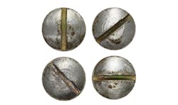
The drive on a fastener is the feature—often a slot, crossed slots, socket, or hex hole—that lets a driver, such as a screwdriver or Allen wrench, apply torque during installation and removal. If the drive is damaged enough upon installation or removal, the fastener becomes unusable.
In some drives, the driver slips out of the drive once the torque needed to turn the screw exceeds a certain point. This process, called camming out, often puts forces on the drive feature and head of the fastener that pushes the fastener’s materials past their yield points, permanently deforming them to the point where the fastener is useless.
Designers can take several steps to avoid damage to the fastener. For example, the drive tool and drive should be appropriate for the amount of torque that will be needed to properly install the fastener. That means the drive (slot or recess) should match the driver being used. There are standards (Industrial Fastener Institute, AMSE) that define how deep the slot or recesses should be, and how far the driver should penetrate into that slot or recess.
The driver’s working surface should also not be so soft or worn that good engagements are impossible to achieve.
Image courtesy of Thinkstock
Fastener Corrosion
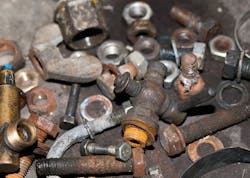
Elements such as sulfur, sodium, and chlorine can combine with moisture in the air and the environment to form hydrochloric and other acidic compounds. These compounds can corrode the working surfaces of fasteners and make them unreusable—or worse, fail catastrophically. This is especially true for fasteners exposed to the outdoors or dirty environments.
To reduce the risk of corroding fasteners, designers should specify ones made of corrosion-resistant materials. Another tactic is to avoid having dissimilar elements in close contact in an assembly, thus reducing the level of galvanic coupling and lowering any electrochemical potential differences that lead to corrosion. A third approach is to put sacrificial coatings on fasteners and assemblies at risk of corrosion. These coatings corrode first, leaving the structural parts of the fastener and assembly intact.
Engineers and designers can also conduct corrosion testing on assembly and fastener materials and coating before production. The results will highlight factors that can lead to rapid corrosion and gives designers the option to use other materials or avoid those factors. It’s also critical that the materials and coatings used for fasteners are not nicked or scratched due to rough handling during transport, storage, and assembly. An initial coating of light oil and periodic recoatings help stave off corrosion due to nicks and scratches.
Debris in Fastener Drives
Fasteners with recessed drives, such as a Philips, Pozi-Drive, Frearson, or socketed type (such as a six-lobed or hex recess) often accumulate grit, grease, and lubricants in the drive. This reduces their ability to transmit torque during removal and reuse, and makes fasteners prone to camming out even more likely to do so. To identify drives that cam out too easily, conduct tightening torque tests on several drives before finalizing the fastener selection.
Another tip is to place fasteners where they are shielded from debris and dirt. If this cannot be done, apply protective grease or lubricant that can be easily flushed out of the drive prior to removing the fastener. In one instance, a company filled the drives of socket-head cap screws used in a coal-pulverizing facility with potting compound. This kept out the coal dust that was rendering the fasteners difficult to remove and impossible to reuse.
Image courtesy of Thinkstock
Threads Seizing Due to Friction
Galling and seizing threads make machine screw threads useless, either by requiring more loosening torque than the fastener’s drive can transmit or by raising the thread’s coefficient of friction, K, to a value of 1 (friction therefore consumes all of the applied torque). Threads can be “welded” in place by friction forces that meld together the high spots and surface roughness on the thread’s pressure planks.
One fix for this problem is to use mating threads that won’t gall (non-galling metallurgy) or to separate the pressure flanks and bearing surfaces of the fasteners with the right lubricating and anti-seizing compounds. This is particularly useful for stainless-steel threaded fasteners.
Threads Seizing from Heat or Corrosion
In applications with high temperatures, the fasteners’ mating-thread pressure flanks, as well as the crests and roots, can seize. This is particularly true when the fasteners and the material they are installed in are dissimilar, with different thermal expansion coefficients. In such cases, designers should be sure there is adequate clearance and temperature-appropriate thread lubricants, and that anti-seizing compounds are used.
Image courtesy of Thinkstock
Vibration Damage
Vibrations can loosen fasteners to the point that they fall out of assemblies and are lost, or else drop into working components and damage them. Even if they don’t fall out, loose fasteners can hammer back and forth and fatigue themselves along with previously well-clamped parts.
To avoid excess vibrations on fasteners, analyze the assembly’s vibration modes and do not install fasteners where there are resonances and undesirably strong vibrations. Non-metallic fasteners could also help by damping vibrations with elastic attenuation. Self-threading fasteners and supplemental locking features, if needed, can also provide relief from vibration-induced problems. These features include locking threads, plastic inserts and coatings, commercial thread-locking adhesives, metal locking devices, underhead serrations, and locking washers, all of which can be evaluated prior to the final design.
A good evaluation test is to measure the torque needed to install the fastener, a value called the prevailing-on torque, and the amount of torque needed to remove the fastener after one installation (called the prevailing-off torque for first use). Then repeat this procedure, taking note to record the prevailing-off torque after five installations (the prevailing-off torque on fifth removal). The ratio between the prevailing-on and -off torques, as well as the percentage drop between the first and fifth off-torque, are good indicators of the fastener’s vibration resistance. The lower the ratio, the less the loss of vibration resistance when reused.
Metallurgical Fatigue
Fatigue obviously shortens a fastener’s life and reliability. To prevent metal fatigue, designers should ensure the preload is greater than the service loads and make the assembled joint rigid with respect to a fastener’s spring rate. Another step designers can take to prevent catastrophic failures is to know fastener endurance limits and replace them when those limits are being approached. And if there is any concern or issues, use liquid penetrants and magnetic particle inspection methods on assemblies and fasteners, so as to detect micro-sized cracks before they propagate and cause problems.
UV Damage
Plastic fasteners can degrade and lose performance if exposed to sunlight and its UV radiation. Designers should be aware of how much any plastic fastening components will degrade when exposed to UV radiation and provide shielding for them, or else look for alternative materials.
Image courtesy of Thinkstock
Loss of Locking Ability
Lock washers, locking tabs, thread-locking adhesives, and a wide range of self-locking types of threads are not reusable if installed or applied improperly. It’s important that designers and technicians, as well as anyone who will work with these devices, understand their working principles—including the locking features, their performance, and how to properly install and remove them.
They should also be aware of any precautions needed when using them, such as the need for clean threads when using thread-locking adhesives, and that metal surfaces should be burr-free and intact when using metal-locking elements. If necessary, a company should ensure all proper fastener procedures, precautions, and rules of thumb are documented and passed on to all designers and technicians involved with fasteners.
A relatively new approach to locking the threads on machine screws uses tape, which puts the locking feature in the tapped holes rather than on the installed fastener. The pressure flanks of the internal threads have a secondary locking ramp rather than the standard 60-deg. angle. During installation, the pressure flanks of the external threads are elastically deflected slightly to provide more friction, making them less likely to lose their locking capability.
Thread Wear
Machine screws that are often installed and removed, or frequently loaded and unloaded, can see significant wear and tear. Repeated loading can deform the loaded threads, which increases stresses on the thread loads flank on the remaining area of the screw thread’s flank. To minimize this damage, designers should carefully select appropriate thread materials and finishes. For example, a bad selection would be to put relatively abrasive zinc plating on contact surfaces because it can gall and wear down at high spots, and this can loosen the thread fit. Harder finishes such as electroless nickel adds both hardness and lubricity to minimize wear from frequent use.
Wear from cross-threading and mis-starts can be reduced or eliminated by adding locating features such as chamfers, pilots, and full dog points.
Click table to enlarge
Loss of Bearing Area
Loss of bearing area due to compression and distortion can be avoided by calculating the stresses on the thread-bearing area and balancing the bearing strength and fastener area. But designers need to understand the bearing strength of both the material being joined and the fasteners, along with the fastener’s footprint on that material. A pair of snowshoes provides a good analogy. If the snow’s (material being joined) bearing strength is below a certain level, a person sinks when walking (or clamping) in normal shoes. But increasing the bearing area with snowshoes spreads the load and reduces the bearing strength needed of the snow, letting the person walk on top of it.
Here’s an example: A screw has a 0.25-in. diameter head. It also has #6-32 threads, which gives it a shank diameter of 0.138 in. Its fillet radius is 10% of the shank diameter or 0.1(0.138) or 0.014 in. And the clamp load is 1,200 lb. The inner diameter is then comprised of the shank plus twice the filler radius or 0.138 + 2(0.014) or 0.166 in.
To find the bearing area, subtract the inner diameter area, from the outer diameter area or 0.7854(0.25)2 − 0.7854(0.166)2, or 0.0274 in2.
This is the screw’s effective bearing area, assuming the bearing surface is perpendicular to the shank. The shank is usually within 2% of perpendicular (a common tolerance). If it is less perpendicular, the bearing surface is smaller and localized stresses, which are measured in psi, are higher. Bearing stress is then found by dividing the clamp load by bearing area 1,200 lb./0.0274 in.2, or 43,723.8 psi, or about 44,000 psi.
Localized stresses can plastically or permanently deform the underside of the fastener’s head. And if the fastener is installed in a material with compressive yield strength less than 44 ksi, which could occur if it were wood or a low-modulus thermoplastic, the material could be permanently compressed, leading to a loss of clamp load and possible damage to the assembly. To avoid these issues, designers could use a fastener with a larger bearing area or include a washer in the design. It would also be important to ensure bearing perpendicularity stayed within tolerance.
James A. Speck, SPEC ENGINEERING, LLC
This article is excerpted and edited from Mechanical Fastening, Joining, and Assembly, 2nd ed., by James A. Speck, published by CRC Press, Taylor & Francis Group.


