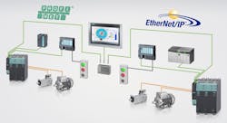
What is Ethernet?
Ethernet is the major local-area network (LAN) in which we connect our computers, routers, and printers. It has taken an important role in the industrial engineering world, having become the established standard connection for the Internet of Things.
According to Cisco in 2003, Ethernet makes up 85% of the world’s LAN connections. Industrial Ethernet differs from commercial Ethernet in that it applies the Ethernet standards toward the development of data communication to control and operate manufacturing networks.
Beginnings of Ethernet
ALOHAnet was a wireless data network that connected several computer systems separated throughout the Hawaiian island college campuses. They attempted to have independent data radio nodes to communicate with each other on a peer-to-peer basis without interference. ALOHAnet’s solution was a multiple access with collision detection (CSMA/CD) concept. This idea inspired Bob Metcalfe from Xerox to base his PhD studies on finding improvements.
In the initial days of the Ethernet, there were two common options for configurations: 10Base2 and 10Base5. The operating speed for both configurations was 10 Mbps and used coaxial cable with nodes via tee connectors or through attachment unit interfaces in a multi-drop bus configuration.
The unit interfaces or nodes are typically computers with network interface cards (NIC). The max allowed segment lengths for 10Base2 was 185 ft when using RG 58 coaxial cable, also known as “Thin Ethernet.” 10Base 5 offered greater distances between segment nodes; however, it required thick coaxial cable which was difficult and bulky to manage.
Other configurations started to develop, such as 10Base-FL, which allowed networks to use fiber optic media and increase distances to greater than 2,000 ft. 10Base-T became a popular physical layer option due to its ease of install and use of inexpensive unshielded twisted pair (UTP) Category 3 (CAT3) cable. Each computer is required to be less 100 feet from each other with standard RJ-45 connectors. By the 1990s, 100 Mbps Ethernet equipment became available. These NICs would adjust automatically between 10 Mbps or 100 Mbps operating speed.
Today’s standard for computer setups is to have NICs implement 100Base-TX. Category 5e UTP cables (CAT 5) are the standard, with the lengths the same as used with 10Base-T networks—100 ft or less. What was once a coaxial-based network is being replaced by fiber optics specifically for point-to-point links. 100Base-FX uses two optical fibers for full duplex point-to-point communications which a reach 2,000 ft. Gigabit Ethernet or 1000 Mbps connections are available using twisted pair and fiber optic media.
Ethernet Data Link Layer and Frame
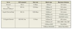
Ethernet specifies the physical layer and data link layers of a network’s function. It became the basis for the IEEE 802.3 network standard. The physical layer specifies electrical signals, signaling speeds, media, connector types, and network topologies. The technology can be used over optical fiber and twisted pair-cables. Four different type of data rates are:
The data link layer defines the media access method. Half-duplex link are those connected in a bus or star topologies: 10/100Base-T, 10Base2, 10Base 5, etc. They use carrier sense, multiple access with collision detection (CSMA/CD). This allows for multiple nodes to have equal network access. All nodes on an Ethernet network continuously monitor for transmissions on the given media.
Nodes wait for a network to be idle prior to starting a transmission. When nodes transmit at the same time, the signals overlap and corrupt the originals. When nodes see a different signal from the one they are trying to send, they detect the collision and stop transmitting. They re-attempt to transmit after a preset delay. This method of media access allows for nodes to be simply added or removed from a network.
A node once connected begins to listen and transmit on the network. This, however, will eventually lead to decreased access and an increase in collisions. This makes Ethernet networks probabilistic networks. In full-duplex point-to-point Ethernet links like 10Base-FL or 100Base-FX collisions are not an issue. This is due to the fact that only two nodes are present and there are separate send and receive channels available. Data can also be sent in both directions simultaneously, hence doubling the data transfer rate.
The Ethernet Frame defines the format of the data message sent on the network. The message format contains several fields of information, including the data to be transferred. The data unit is defined as the actual data to be sent and can contain between 46 and 1500 eight-bit bytes of binary information. The length of the data unit is determined and included in the message as a field for the receiver to determine which part of the message is data.
The MAC address is the six-byte binary number set which includes the source and destination information for the nodes. A MAC address is included in each message sent over the network, and each Ethernet node has a unique MAC address.
The data link layer specifies the frame structure of messages transmitted or received and how communication occurs over the media. Nodes, switches, and hubs can be added and removed simply, and the technology can be easily troubleshot. These factors have made Ethernet connections the new standard for industrial network applications. The functions of the OSI layers are to designate how data and application demands are transmitted.
There are seven layers in the OSI reference model. The lower layers (1-4) focus on data-transport, while the upper layers (5-7) focus on applications. The lowest layer (1) is the physical layer closest to the physical network medium. The physical layer and the lower data link layers are implemented in hardware and software such as cabling, or Ethernet (which exists on Layer 2).
Layer 3 is used for logical addressing and routing. Its most common application is the use of the Internet Protocol (IP). Layer 4 is the transport layer that ensures the data is delivered error-free and in the correct sequence. It uses Transmission Control Protocol (TCP) and User Datagram Protocol (UDP) to transmit data. Industrial Ethernet differs from commercial Ethernet in that it encompass all the lower layers for its solution ,and not just Layer 2.
The upper layers for the OSI reference model are used for application tasks, and are usually implemented for software only. Layer 5 deals with the session. It is responsible for dialing control and synchronization of the session connection (i.e., establishing and managing sessions) between networks and applications.
Layer 6 is for data presentation use. This layer presents the data and coding type, and defines the used characters. It ensures that data may be exchanged between hosts and across the network, and that it is compressed and encrypted. Layer 7 is for application use; it is used by software to prepare and interpret the data. As the top layer, it is closest to the end user.
Ethernet Connection Types and Industrial Systems
TCP/IP over Ethernet networks offers the possibility of a level of standardization. Historically, network applications based on time-critical processes have used deterministic networks. When using Industrial Ethernet, it is important to note the speed and determinism of the communication. Speed is how fast the network can send information over the Ethernet.
Determinism is the network’s ability to communicate in a predictable timespan. For motion control systems, it is essential for Ethernet connections to transmit data to and from devices on a regularly scheduled basis. These are networks based on master/slave or token passing schemes.
The use of Ethernet networks must be controlled at levels no greater than 10% or they would suffer from inadequate performances. Segmenting networks via switches and routers minimize unwanted network traffic and reduce use. Another method is to use newer and higher-level protocols to incorporate prioritization and synchronization of messages to ensure better timed delivery.
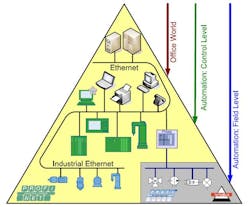
The result of these methods is shift of using Ethernet for industrial control on the plant floor and into the cell field levels. This increase of Ethernet implantation is due to their ease of installation and low cost of hardware. The use of bridges and fast switches help raise the determinism of a network. Eventually as gigabit, 10Gbit, and 100Gbit become more commonly used, determinism concerns will reduce.
The major Ethernet connection types are:
Modbus TCP/IP
- First industrial protocol on Ethernet, introduced in 1999.
- Based on Modbus protocol, which was developed by Modicon in 1979.
- Advantages:
- Uses standard Ethernet layers: hardware and TCP/IP transport layer
- Open and relatively simple Ethernet protocol
- Disadvantages:
- Not a hard real-time protocol
- Largest supplier: Schneider Electric
- Multi-vendor consortium: Modbus IDA
- Factory automation technology: RTPS
EtherCAT
- Open-source, based on IEC 61158 and other similar standards.
- Advantages:
- Hard real-time industrial protocol
- Efficient and straightforward communication
- Disadvantages:
- Total number of devices used is limited
- Not designed for standard TCP/IP packets and EtherCAT packets
- Largest supplier: Beckhoff
- Multi-vendor consortium: EtherCAT Technology Group (ETG)
- Factory automation technology: Shared Frame
Ethernet/IP
- Extends DeviceNET concepts to Ethernet
- Advantages:
- Uses Ethernet transport layers (i.e., TCP and UDP)
- Disadvantages:
- Networks can be overloaded with UDP messages if not correctly configured
- Largest supplier: Rockwell Automation
- Multi-vendor consortium: Open Device Vendors Association (ODVA)
- Factory automation technology: CIP
Profinet
- Application protocol that extends Profibus to Ethernet
- Advantages:
- Supports both standard and deterministic Ethernet traffic
- Implements IEEE 1588 and Quality of Service (QoS) to add determinism
- Disadvantages:
- For Real Time and Isochronous Real Time managed switches, QoS is recommended
- Largest supplier: Siemens
- Multi-vendor consortium: Profibus and Profinet International
- Factory automation technology: Profinet IO
