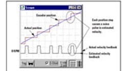
Sevos can by noisy. One of the main culprits is the resolution limitations of encoders or resolvers coupled with resolver-to-digital (r/d) converters. In both cases, the servo controller knows the position imperfectly - to within a least-significant bit (LSB). When the servo controller estimates velocity, the resulting signal contains pulses that lead to current spikes and hense, noise.
Most modern servo controllers sense position rather than velocity. Because position is fed back digitally from an encoder or resolver, the signal is quantized to a least-significant bit. For example, a 1,000-line encoder can provide up to 4,000 counts for each revolution of the motor using quadrature. The resolution of such an encoder is 1/4,000 of a revolution.
Digital drives cannot watch the position continuously. Instead, they sample it at regular intervals, say, every 250 μs. At each sample, most drives estimate velocity from position using a simple formula: V = (PN - PN-1)/T where PN is the most recent position, PN-1) is the position from the last sample, and T is the interval between samplings.
Estimating velocity from the two positions works well except for the problem of resolution. The noise from this estimate travels through the servo loop and produces current spikes, which often result in noisy systems.
Almost all resolution noise is generated from the proportional gain in a velocity loop. In fact, for the purposes of understanding resolution noise, we can think of the servo loop as a simple proportional controller. While position controllers and integrating velocity controllers are more common in industry, the proportional gain generates most of the noise. Our simple loop forms a velocity error and then amplifies it with KVP and filters it.
The most responsive feedback systems require the largest gains. When a servo system must move quickly, KVP will be relatively large. All control loops have a proportional gain, even those that don't contain a KVP term. For example, PID position loops use the "D" gain for the same purpose as our velocity loop KVP. Responsive systems have a large KVP, or equivalent, which amplifies noise.
Large load inertia also means the system will be noisier. Think of a motor as a control element. When the inertia gets large, the motor gain is low; it's hard to accelerate. With this low gain, you must have a large electronic gain to compensate. Raising inertia increases KVP, making the system noisier. Systems that are highly responsive or have large inertias need high resolution feedback signals.
An easy way to help the noise problem is to add filtering in the loop. You can do it by filtering the feedback signal directly, filtering the signal in the forward path, or by using the current loop as an implicit filter.
Filtering reduces current noise amplitude either directly through a forward filter and current loop, or indirectly by filtering the velocity signal in a feedback filter. Unfortunately, filtering also causes overshoot and instability. If you cannot fix the noise problem without degrading servo performance, you must increase the resolution of the feedback.
The controller shows a step response. The command (black) and response (blue) are at the top and the current (brown) is at the bottom. The more noise on the current signal, the noisier the servo system. The default configuration uses essentially infinite resolution (1010 lines) and so there is no measurable noise. However, when you enter a realistic value for resolution, such as 2,500, you'll see it grow.
Notice also that when you increase the inertia, doubling it for example, you need to increase the KVP gain by the same amount to maitain servo performance. Remember, though, that noise increases proportionally with gain.
System responsiveness can be increased by raising the gains. For example, KVP can be raised to about 1.1 before non-resolution problems occur. But raising it also increases noise, demonstrating that larger inertia and higher responsiveness increase system sensitivity to resolution noise.
You can also add filters and change the frequencies for the forward filters (LPF1, LPF2) and current loop. The feedback filter is fixed at 400 Hz. Notice how using more filters, and ones with low bandwidths of about 150 Hz, helps the noise but degrades the servo performance.
Where to find more counts
Applications that demand the highest reponsiveness or have very large load inertias need high resolution. With enough filtering, you can reach the required response rate.
Fortunately, there are other techniques to increase resolution. For an encoder, increase the line count. Sometimes this may not be an option because high line counts reduce encoder speed. Some servo controllers support 1/T or clock-pulse counting, a technique that increases resolution by improving on the simple difference.
If using a resolver, you can interpolate analog "ILSB" signals from some r/d converters to increase resolution. A final option is using a sine encoder, which divides each encoder line into 1,000 positions, increasing resolution well beyond any equivalent standard encoder.
Reference
Application note ASU010H is available from the author or from www.kollmorgen.com.
