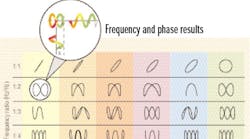
The usefulness of a test depends on how descriptive the results are. With the help of transducers, oscilloscopes are used to probe, monitor, and calibrate all kinds of systems. When set to return Lissajous figures, they graphically show the frequency and phase variations between compared signals. That’s essential to seeing the whole picture for time-variant situations, because only complex-valued results express the instantaneous relative movement of monitored points. A parametric equation, the Lissajous curve is a two-dimensional function described by a pair of equations — x=cos(nt), and y=sin(mt+a) — plotted against one another to visually reveal system relationships.
Questions & Answers
Q: What’s a common use of Lissajous figures?
A: Calibration. Based on the idea that the nonlinearities of devices contain useful information, outputs from twin encoder detectors can be plotted against one another to reveal sensor miscalibration. Potato-shaped plots imply imperfect alignment of the light source, encoder disc, and/or photodetectors.
Q: Does the type of oscilloscope affect results?
A: Yes. Originating with cathode-ray oscilloscopes, Lissajous measurements are best displayed in analog, where electrical variations can actually be seen as they steer electrons into a phosphor screen. Because of electron mobility, extremely quick changes can be detected. Unlike typical digital scopes, analogs have no problem creating real-time x-y displays; they take data continuously, so no gaps in Lissajous figures result. However, analog scopes are typically limited to a few megahertz of bandwidth. Some digital phosphor oscilliscopes that model analog scopes offer the best of all worlds – they acquire and display genuine x-y plots in real-time, using a continuous stream of digitized data. As with analog scopes, digital phosphor scopes can also display an x-y-z image with increased intensity at points where the signal dwells.
Q: How does damping relate to Lissajous results?
A: A system’s natural period is excited when the Lissajous figure closes. With little damping, the figure can be extremely sensitive to resonance, even to 0.1%. This means that measuring the isolation caused by faults provides a very sensitive equipment malfunction check. But more damping is often desirable to reduce settling times. To determine the damping constant, the phase angle is measured for different periods. If large phase angle changes occur with small driving frequency changes, then there is little damping.
