Tuning a control system is a lot like balancing a budget. The laws of physics, like those of economics, often require you to give up one thing to get something else.
If you want your controller to respond quickly, for example, you might have to put up with some overshoot. If the application doesn't tolerate overshoot, however, you may have to settle for a less responsive system. For each application, there's an optimum balance between system response and stability, and that's what control-loop tuning is all about.
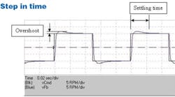
One way to gauge loop performance is to look at the time-based response to a step command. Overshoot (the ratio of the peak to the final value) is a measure of stability, while settling time (the time it takes the signal to settle within, say, 3% of its final value) tells you how responsive the system will be.
Similar information can also be found in a frequency-response, or Bode, plot. Given a sinusoidal input, any linear system will produce a sinusoidal output of the same frequency. In fact, if you were to go around all the nodes in the network with an oscilloscope, you'd find that every signal has the same frequency as the input. The only differences would be the amplitude and phase.
A Bode plot is simply a diagram that expresses the relationship between input and output signals. It consists of two parts: a gain curve and a phase curve. The gain curve is the amplitude ratio expressed in decibels:
G = 20 log(Xo/Xi) dB
where Xo = output amplitude and Xi = input amplitude.
The phase curve is the time delay td expressed in degrees:
Φ = tdfin 360 deg where fin = input frequency (Hz).
Gain curves tend to be the easiest to interpret if you're trying to get a handle on stability and response. For the latter, your best bet is to look at bandwidth, the frequency where the gain falls to -3 dB. In general, the higher the bandwidth, the more responsive the system.
If you're concerned with stability, you can get a pretty good idea from the amount of "peaking" in the curve. A peak of more than 1 or 2 dB, before the gain plot starts to fall, is usually considered excessive.
Bode plots for motion systems share many similarities. Typically, they have a gain of 0 dB at low frequencies, which declines as frequency increases. This is to be expected. At low frequencies, the output of a motion system should be able to precisely follow the input. But at higher frequencies, the motion system cannot keep up, hence the fall off in gain.
Bode plots can be simulated or measured directly. Simulated plots are adequate for teaching and for providing feedback in the preliminary stages of design. However, if you're working on an actual prototype or a machine in the field -- say, trying to pinpoint sources of mechanical resonance -- you'll probably want to use a dynamic signal analyzer (DSA) to obtain Bode plots from direct measurements. DSAs are available from several sources, including Hewlett-Packard, Schlumberger, and DSP Technologies.
Test your tuning skills
If you want to learn more about Bode plots, log on to ptdesign.com and download the ModelQ simulation package.
After installation, click "Run" and select the March model from the combo-box at the top of the screen. Then click on the "Constants" tab and start adjusting the loop gains until you get a good time-domain response. To run a Bode plot, press the "Go" button. If you want to find the -3 dB point, click the auto-find button with the magnifying glass.
Because the example is not tightly tuned, you should be able to improve responsiveness (increase bandwidth) without causing instability (peaking). At about 200 Hz, however, you'll notice that the system starts to become less stable.
Continue to experiment and try to develop a feel for the relationship between bandwidth and settling time, along with peaking and overshoot.
Moving in stereo
Pick-and-place machines – like the ones used in electronic board assembly and numerous back-end semiconductor processes – bring to light the challenges and compromises involved in control-loop tuning. Consider the x and y motion axes. On the one hand, they need to be fast. Pick-and-place machines typically move thousands of parts per hour, so saving just a few milliseconds in settling time can significantly improve throughput. This translates into high bandwidth. In fact, it's not uncommon to see design specs calling for bandwidths over 200 Hz.
Increasing bandwidth comes at a price, however. It's called overshoot. Unfortunately, many pick-and-place operations don't like overshoot one bit. Often, parts must be placed within a hair's width of a solid barrier, so even the smallest amount of overshoot could be disastrous. Obviously, there are compromises to be made.
