In 1967, unbeknownst to many, the world began marching to the beat of a different drum. With little fanfare, the natural frequency of atomic Cesium became the international unit of time. Today, Cesium clocks, ticking away at 9,192,631,770 Hz, keep track of the hours and minutes to within a millionth of a second per year, helping the world stay in synch and on schedule.
Now when it comes to measuring distance, light is the modern yardstick. The most precise definition of a meter, for example, is the length light travels in a vacuum during 1/299,792,458 of a second. Light also plays a role in many industrial displacement sensors, the newest and most unusual of which is an interferential linear encoder.
Unlike ordinary optical encoders that rely on flashing (interrupted) light, interferential encoders work on the principle of interference, the positive or negative interaction of two or more light beams. Naturally sensitive to the movement of optical surfaces, interference provides a means for registering incredibly small displacements.
Why interfere
Precision demands precision. When chipmakers squeeze line widths on semiconductors, they have to exact that much more precision from their tooling. If new tooling is required, it, too, must be manufactured and assembled with proportionally tighter tolerances. This sort of domino effect also occurs in medical systems, machine tools, and printing, packaging, and material-handling equipment.
Optical interference as a means of achieving higher precision may seem like a reach. How can an ethereal property of light characterized by artsy contrast patterns be employed for any sort of useful work? But in fact, interference is based on phase, a direct multiple of the wavelength of light. With appropriate instrumentation, it can be used to accurately measure physical displacements on the same small scale.
Bright idea
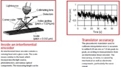
One sensing arrangement that seems to work fairly well is modeled after conventional optical encoders. It consists of a scanning head and a glass scale. The scale is made of Zerodur (a glass ceramic) imprinted with chromium lines on 512-nm centers. The scanning head, which moves relative to the scale, incorporates a light source, index grating, cube-corner prism, and three photodetectors.
The collimated light that comes off the source is perpendicular to the direction of travel but oblique with respect to the lines on the grating. Upon hitting the grating, the light is diffracted into three orders. Only the 1st orders strike the scale, diffracted by the prism in such a way that both beams arrive in parallel offset. The beams are then diffracted again, reflected, and finally interfere on the index grating away from the incident light. Photodetectors convert the 120° phaseshifted beams into electrical pulses, which are then transformed into standard quadrature signals.
The role of the prism is especially important. Besides bending light, its two-fold diffraction effectively reduces the signal period by a factor of four to 128 nm. Ultimately, the measuring step is reduced even further, to 1 nm, through electronic interpolation. Having the prism in the optical circuit also alleviates mounting tolerances that might otherwise be unbearable because of the fine scale pitch.
Perhaps the main advantage with this sort of sensing system is that it produces a signal without harmonics. As a result, there are no short-range nonlinearities to contend with. Interpolation depends only on the offset, amplitude, and phase difference of the signals — quantities that can be precisely adjusted.
Measuring error
Although interpolation error is controllable, measuring and verifying it is difficult. With a measuring step of only 1 nm, the associated inaccuracy will likely border on the unmeasurable. In fact, standard techniques based on heterodyne interferometers prove useless.
What does work is a method that leverages the precision of the interferential sensor itself. The approach is this: Establish a reference length, namely the fixed scale pitch of 128 nm, then move the scale relative to the scanning head by fractions of this amount. In the actual setup, a piezoelectric positioning system with a scanning range of 15 μm translates the scale, while a signal processing board with an interpolation factor of 4,096 provides control.
To compensate for noise in the piezo system, the developers resorted to a common geometric trick. Instead of aligning the translator to the measuring axis, the piezo system is rotated by an angle of 88°. As a result, the scale moves at an angle slightly oblique to the “tick marks,” so the actual displacement ΔL = 15 μm is reduced by a factor k = cos a ≈ 1/28. The displacement in the measuring direction of the scale is thus about 530 nm, corresponding to slightly more than four signal periods. The noise in the piezo system also scales by the same amount, 1/28, bringing overall resolution in line with anticipated interpolation error.
Using this arrangement, the interpolation error is measured over several periods. The difference between the piezo system’s actual and measured position is a parabolic curve which, when subtracted from subsequent measurements, yields the interpolation error. This error is a mere ± 50 picometers, comparable to the Bohr radius of a hydrogen atom. To rule out other possible error sources, the test system is easily de-adjusted – on the basis of on-off ratio, amplitude, and phase – and the results re-verified.
Dr. J. Thiel and E. Spanner are responsible for interferential product development at Dr. Johannes Heidenhain GmbH, Traunreut, Germany.
Special thanks to J. Streitwieser for his technical assistance.
