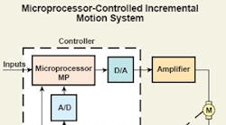
Today’s electronic control is becoming ever more proficient as new microprocessors, digital signal processors (DSPs), and similar electronic devices supply the control platform with tremendous computing and process timing power.
The microprocessor began to proliferate into many motion applications in the late 1970s. By 1976, the Intel 8080 and Motorola 6800 microprocessors were being used to control step motors via complex control algorithms with lower system costs and without complex logic control circuitry. A year earlier, T.R. Fredriksen presented the microstepping control strategy at the Incremental Motion Controls and Devices Symposium.
The key to more effectively controlling step motor velocity jitter was to divide the phase current into smaller increments using a two-phase rotating sine vector pattern. The smaller increments or microsteps (typically 8 to 32 microsteps per full step) reduced velocity jitter, torque ripple, and motor resonances, providing better open-loop motion stability than previously achievable. The microprocessor was the most suitable device for controlling digital (stepby- step) motion. These two developments, one hardware and one software (algorithm control), opened the precision motion market to digital systems and the step motor. The principle of accelerating and decelerating the step motor’s motion without unwanted velocity overshoots could be achieved with various step timing strategies in many applications by using the rapidly improving family of microprocessors.
By 1970, the brush dc motor had replaced the two-phase ac “control” motor as the prime mover in servosystems. The high-performance attributes and linear operating characteristics of the PMDC brush motor, initially using Alnico and then rare earth magnets, were offset in many applications by brush life concerns. By 1976, the analog servosystem using rare earth PM brush dc motors was being used extensively in the office automation (OA) and factory automation (FA) markets.
Brushless dc motors were replacing both ac induction and dc brush motors in spindle drives for larger storage disk drives (14 and 8 in.). Head positioners in floppies were using can stack PM step motors. Hybrid step motors were the head positioner of choice in the new 5 ¼- in. Winchester disk drives in 1980. Most electronic printers used PM or hybrid step motors in their ribbon and paperfeed systems.
Brushless PM motors in machine tools
The first brushless PM motors for machine tools (FA) in 1981 used sinusoidally shaped back emf waveforms and the sixstep commutation technique to achieve smoother velocity over a wide speed range than possible with trapezoidal back emf waveforms. Smooth motion at speeds less than 100 rpm was readily achievable with this quasi-sinusoidal commutation scheme. Others were experimenting with sinusoidal current control to achieve the lowest possible velocity ripple over a side speed range. The sinusoidal current drive and sinusoidal back emf brushless PM motors would await better microprocessors and the arrival of the DSP to achieve smooth, controlled motion down to fractions of an rpm by the mid-1990s. The “new” motor name, the ac servomotor, or the ac PM servomotor, was first used in the early 1980s to describe the inverter driven PM brushless motor with sinusoidal control.
The main technology force for all precision motors is the continued evolution of both logic and power electronics. New power electronic devices joined microprocessors and other logic ICs in providing more efficient and higher power devices as represented by the bipolar transistor in the early 1970s and the MOSFET at the end of the 1970s. Packaging these devices into a step or servomotor drive moved in various directions. The PC board with integrated heat sinks for the power devices was used extensively. On-board logic circuitry became available for servodrives or amplifiers for controlling motor commutation, current, and velocity control. The servo boards were analog with output voltage signals from the generators as a function of speed providing the precision velocity signal measurements for use in the servosystem. Many servo drives (amplifiers) were installed in 19-in. rack configurations at that time.
Transistorized drives emerge
By 1982, the transistorized brushless dc power bridge was supplied by many manufacturers to the U.S. servo market. The SCR drive system in its three most popular forms was seriously challenged by the transistorized pulse width modulated (PWM) drives for brush (four power transistors) and brushless (six power transistors). The transistorized servo drive was more efficient with faster time responses and higher position loop gains, equating to better system response. The transistorized drive was significantly smaller than the earlier SCR servo drive packages and more thermally efficient. By 1985 the SCR servodrive was fading from use and replaced by the transistorized PWM servodrive.
Stepmotor drives switched to transistorized drives with the microprocessor furnishing step pulse timings for acceleration, deceleration, and last-step damping functions. Microstepping was also readily handled by the microprocessor. It provided a strong motion control base for step motor drives. By 1985, the bipolar drive was replacing the unipolar drive and chopping (similar to PWM) drives were beginning to move into the U.S. market.
New step motor types appear
Two new hybrid step motor developments started gaining market share in the early 1980s. The first was the five-phase step motor developed by Berger-Lahr in Germany and Oriental Motor (a licensee) for the U.S. market. The second development, the enhanced hybrid step motor, was introduced in 1983 by Sigma, now part of Danaher Corp. It provided a 50 percent increase in torque without any change in unit size. This new hybrid step motor opened up many applications not available to step motors in high-performance positioning systems.
By the end of 1985, the step motor, led by the PM can stack step motor in OA and the hybrid step motor in FA, was the first choice of many moderate and highvolume position applications. The openloop control scheme with the availability of microstepping was easier to implement with new microprocessors in all but the most demanding positioning applications. Lower cost full step/half step motor drives remained in use in higher volume OA applications.
