Despited the advantages of digital motor drives - from software programmable tuning gains to internal supports for feed-forward and s-curve velocity profiles - they do have a few weaknesses. Digital signal processing, no matter how fast, introduces delays in the control loop. As discussed in last month's column, this can cause phase lag and, ultimately, stability problems.
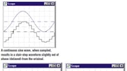
Digital systems operate in discrete time steps. At regular intervals, the controller reads the feedback and command information, executes control algorithms, and outputs a signal to the current loop. Between intervals, the output to the power converter is held at a fixed level. This is what gives digital control waveforms their characteristic "stair step" appearance.
The data stream in a digital motion controller involves three major types of delay: sampleand- hold, calculation, and velocity estimation.
Sample-and-hold: Any processing method that uses stored data is subject to delay. Consider a digitized sine wave produced through sample-and-hold.
At the beginning of the sampling period (just after the vertical segment), each data point is fresh and accurate. But during the sample interval, the information ages. At the end of the sample, the data points are approximately one sampling interval old. The average age of the data over the interval T is, therefore, T/2. In other words, the sample-and-holds adds a delay in the loop of T/2.
Calculation: Calculation delay is due to the time required to execute the control laws and calculate the current command. Unlike analog systems which process signals continuously, digital systems require a certain amount of time after sampling to calculate the current loop command.
Calculation delay can vary anywhere from a fraction of a sample interval to nearly the entire interval. It is a function of the complexity of the control laws and the skill with which they are coded.
When considering a new controller, you'll probably have to contact the vendor to obtain estimations for calculation delay. You'll find that it is often too large to be ignored. To be safe, you should at least consider this delay along with the sample rate when selecting digital controllers.
Velocity estimation: Velocity estimation delay comes from using position feedback sensors such as encoders and resolvers to estimate velocity. Here, most controllers take the difference between the two most recent positions to approximate velocity:
Vn = (PN - PN-1)/T
Velocity estimation delay is equivalent to that of a sample-and-hold delay. Consider that the difference on which the calculation is based spans consecutive data points, PN and PN-1. Thus, the average age of the data is 1/2 sample, matching that of the sample-and-hold. Motion controllers relying on tachometer feedback, which produces velocity directly, do not experience this delay.
The impact of delay on a digital control system can be rather large. Consider sampling a control system at 1 kHz, assuming a calculation delay of 65% of the sample interval, which puts total delay at 1.65 T or 0.00165 sec.
If the gain crossover is approximately 100 Hz, the loss of phase margin is 0.00165 (100) 3608 = 59.48, which would make almost any system unstable. But change the sample time to 0.00025 sec – corresponding to a rate of 4 kHz – and the phase loss drops to about 158, which is much more tolerable.
In most cases, you'll find that if the sampling rate can be kept between 2.5 kHz and 5 kHz, digital control systems, though not as fast as their analog counterparts, will be more than adequate for the average application.
Don't delay – use a tach
Ready to explore the effects of sampling yourself? After installation, click "Run" and selet the August model from the combo-box at top center.
You're looking at a digital velocity controller – proportional-integral type – with tachometer or encoder feedback. The encoder is selected by default. If you want to switch to the "tach," double- click to the right of the "Feedback" grid to bring up the adjuster box.
The tachometer measures velocity directly, while the encoder estimates it based on the time it takes the "shaft" to rotate from one position to another. The resulting estimation delay is built into the encoder model.
Continue on page 2
All the delays you might find in a digital controller – including sampling and calculation delays – are incorporated in the system model. By modifying both sample time TSAMPLE and calculation time TCALC, you can see how they effect stability.
Slowing the sample rate, for example, tends to make the system less stable. At some point, when the delays get too long, you may have to reduce the gain KP – and hence the responsiveness of the system – to maintain stability.
On your mark, get set, roll
Printing applications that rely on electronic registration require fast response, and that means fast sampling.
Suppose you want to print something on a moving document carried on a continuous conveyor. Typically, when a proximity switch etects the presence of the document, the print wheel, which is normally motionless, begins to rotate. Your job is to make sure it's at full speed before the document contacts the plate.
This requires maximum responsiveness because there's probably only a few hundredths of a second for the print wheel to accelerate. In most cases, you'll have to provide for at least a 4 kHz update rate in the velocity loop.
