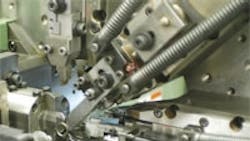
Precision spring manufacturing has never been exact because of the inconsistencies in the wire feed stock and normal wear that occurs in the forming tool. But the Spring Technologies division of Reell Precision Mfg., St. Paul, could change that with a computer-controlled spring forming tool that adjusts for wear in real-time and compensates for material inconsistencies. The result is a process that forms precision springs with high accuracy.
In conventional spring winding, the machine is calibrated and then the springs are formed. Spring tolerances are controlled by sorting after they’re made, resulting in considerable waste and high manufacturing costs. Reell’s process uses an electronic position-control loop and a pizeoelectrically controlled coiled tool that lets the spring winding machine monitor and adjust the diameter of the spring while it’s being formed, eliminating tedious sorting and part disposal.
Reell’s spring manufacturing tool consists of a set of feed rollers that push the spring wire out through a quill. As the wire leaves the quill, the coiling tool bends the wire to create the helical shape. The spring’s diameter is determined by the distance between the quill and the coiling tool, so precise control of this distance is the key to accuracy. If the tool moves farther away, the coil diameter increases. If it moves closer, coil diameter decreases. Measuring the coil diameter as it’s formed and electronically adjusting the coiling tool distance from the quill 400 times per second keeps tight tolerances.
A linear variable displacement transducer contacts the coil as it’s formed, sending a signal to the computer that controls the process. The computer compares this measurement with the programmed value using a PID loop in its software and sends out a correction signal, which is then amplified and sent to a piezoelectric device embedded in the coiling tool. Depending on the correction signal’s strength, the piezoelectric device causes the tool to grow longer or shorter by as much as 0.004 in. — moving it closer or farther away from the quill.
