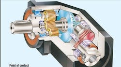
Brushless servos have emerged as the preferred motor technology in material feed applications. They accurately control feed lengths and offer the flexibility to adjust those lengths, plus, they control web tension.
In these applications, designers apply geared speed reducers between the servomotors and various feed rolls throughout the machine to minimize load inertias seen by the motors. An inline speed reducer tends to make the motor-reducer package too long when coupled to the end of a feed roll. As a result, most designers select right-angle reducers. With a right-angle configuration, the motor is mounted perpendicular to the roll axis and doesn’t extend as far beyond the end of the roll as with an inline arrangement.
Right-angle reducers transmit torque using either worm or bevel gearing. Selecting the best type depends on application requirements such as efficiency, size, speed, orientation, and the ability to be backdriven.
Worm gears
A worm gear set consists of a cylindrical worm and a mating helical gear or wheel of larger diameter. The worm has a screw thread that meshes with teeth on the gear. As the worm rotates, its thread slides across the gear teeth to turn the gear and hence the reducer’s output shaft.
Because of this sliding action, worm gears usually have low efficiency - generally between 60 and 70%. High sliding forces also limit reducer input speed to about 3,000 rpm.
The high sliding friction of these gears can cause sluggishness and abrupt response, making them unsuitable for servomotor applications that require rapid and frequent accelerations and decelerations.
On the other hand, worm gears provide large speed reductions, typically up to 100:1. They also have a high tooth contact area, which minimizes noise and vibration, and increases their shock resistance.
Although the worm and gear shafts are at right angles to each other, they do not intersect. They are offset by an amount approximately equal to the sum of the worm and gear radii. As a result, worm gear reducers tend to be larger than other types.
Most of these reducers require oil bath lubrication to combat friction and heat buildup. This generally limits the reducer orientation to one in which the worm is on top, and the gear is on the bottom where it can pick up and distribute oil to the worm. Lubrication in an upside-down arrangement doesn’t work as well.
There are three basic designs: non-enveloping, single-enveloping, and double-enveloping. The non-enveloping design, not widely used, has a cylindrical worm meshing with a helical gear. The worm thread and helical gear teeth make point contact, which limits the suitability of this design to light loads and low shocks.
Single-enveloping worm gears are the most widely used. The worm has a straight-sided cylindrical screw thread, and the gear teeth have curved edges that partially wrap around or “envelop” the worm threads. This design provides medium load capacity and shock resistance.
Double-enveloping worm gear sets have - in addition to curved gear teeth - a worm shaped like an hourglass to achieve greater tooth contact, hence more load sharing. Although this version costs more, the larger tooth contact gives as much as three times the load capacity of standard worm gears. It also provides the most shock resistance.
Bevel gears
Bevel gear sets have conical shapes and they operate on intersecting axes, which are usually at right angles. Unlike the offset axes in worm gearing, mating gears operate in one plane, hence allowing for a smaller speed reducer package.
Gears of AGMA quality 8 or better come in matched pairs to optimize smooth running - they are not interchangeable. Such pairs achieve high performance and accuracy in differentials for instruments.
Mating bevel gears roll, rather than slide, which minimizes frictional losses and yields efficiencies over 95%. In addition, they can use grease lubricants instead of oil, allowing a gearhead to be mounted in any orientation.
Most of them come in either straight or spiral tooth configurations. Straight bevel gears have teeth cut straight across their conical surfaces. They have less tooth contact area than spiral types, with a contact ratio typically about 1.4. Consequently they have less load capacity. Because of the low contact ratio, these gears transfer load from one tooth to the next more abruptly, thereby generating more noise and vibration. These reducers offer speed reduction ratios up to 5:1 and speeds to 1,000 and 8,000 fpm for straight and bevel gears respectively.
Spiral bevels have curved teeth that produce a larger overlap in tooth contact and therefore a higher contact ratio, typically about 2. As a result, these gears carry more load. They also transfer load between teeth more gradually, which generates less noise and vibration. Efficiencies are similar between the two (straight and spiral).
Coming to a halt
The rapid deceleration of a load, such as a material feed roll, is often accomplished by reversing torque in the servomotor. As the motor attempts to reverse itself, kinetic energy of the load dissipates as heat in the motor winding.
But consider what happens when a gearhead is placed between the servomotor and its feed roll. The reverse torque applied to the rotor resists rotation while the roll tries to keep turning, thereby imposing torsional forces on the gear teeth and supporting shafts.
If the gearhead can’t be driven in reverse direction (backdriven), deceleration forces will cause the gears to bind almost instantaneously. This produces shock loading and may lead to premature failure of the gears or other machine elements. On the other hand, if the gears can turn backwards, the load will rapidly and safely decelerate without damaging drive components.
Steve Buffamonte is an applications engineer, Bayside Motion Group, Port Washington, N.Y.
