Day 1
True gearbox rating
Topics of discussion:
Servomotor automation
Repeated dynamic load cycles
Selection of gears
Blindly assuming the dynamic peak torques listed on servomotor data sheets for a design almost always results in over-sized, inappropriately expensive gearboxes. A motor’s acceleration peak torque is never transmitted to its gearbox. In most real applications, a substantial portion of the motor peak acceleration torque is consumed while accelerating the motor rotor. Luckily, for most situations the proper selection of a gearbox or gearmotor is simple. Here is one proven method; its simple formulas and minimal required input data facilitate programming and online sizing routines.
Before using this method for sizing, two conditions should be met: First, the true torque rating must be known. Here, true rating refers to a gearbox’s rating based on endurance limits of its main components — not some ill-defined peak or acceleration torque. Second, the gearbox application shouldn’t involve frequent jams, emergency stops, or other sudden, heavy loadside shocks; these situations require more involved analysis.
Load cycles
Automation, motion control, and positioning applications are characterized by the repeated acceleration and deceleration cycles of starts, stops, and reversals. The resulting characteristic load cycle usually consists of several load peaks of varied intensity and duration, which makes the exact cycle difficult to predict. However, it can be measured and a statistically representative load characteristic cycle compiled.
Typically, when a gearbox must be selected for a servomotor, the exact load cycle is unknown. Having basic load-related data — namely the load inertia and the non-dynamic load torque (friction and gravity loads) — makes reliable and realistic estimations of the required gearbox torque rating possible.
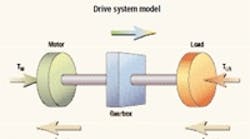
Dynamic torque load equilibrium in a drive train: motor—gear—load
Knowing the peak torque a gearbox is subjected to eases sizing. Consider a system consisting of a motor, gearbox, and load. All system parameters are reflected to the motor axis so that
JLR = JL/i2 and
TLR = TLd/i
where i is the reduction ratio, and JL the load inertia at the output. TL is the true torque at the output; it represents the non-inertial resistance forces the drive has to overcome. Finally, TLR load torque is the friction and gravity-born torque, present in the system under steady state and acceleration phases.
The torque equilibrium equation during the acceleration can be written as:
TM - TLR - JM × a - JLR × a = 0
The torque traveling through the gearbox is:
TGR = TM - JM × a
TGR = TLR + JLR × a
The inertia parameter, which is a function of the system inertia, is defined as k = JM/ (JLR + JM).
By inserting k into (3), torque through the gearbox can be written:
TGR = (TM - TLR) × (1- k) + TLR
This easy-to-handle formula is valid for all motor torque inertia and frictional torque combinations. For long, maintenance-free gearbox life, the calculated gearbox peak load TGR × i should be equal to or below the gearbox torque rating.
Trial run
Consider a typical servo system with an inertia ratio (reflected load Inertia / motor inertia) of 1:1. Because this inertia ratio has the best balance of control characteristics and economics, most system designers aim for this optimal value.
Assuming there are only dynamic inertial loads (TLR=0), with the inertia ratio JLR / JM = 1 the inertia parameter k becomes 1/(1+1) = 0.5, which means TGR = 0.5 x TM.
This implies that in a system with a 1:1 inertia ratio, 50% of the motor peak torque will be consumed while accelerating the motor rotor, leaving only the remaining 50% to travel through the gearbox to accelerate the load. Using the above equation, an appropriate gearbox can be selected based on the calculated maximum output torque requirement of TGR x i instead of selecting one based on the full peak motor torque TM× i.
