Transmitting rotary motion into a vacuum chamber, whether in semiconductor manufacturing equipment, optical coating chambers, or highspeed X-ray anodes, is no simple task. Combining the necessary sub-components is often complicated and time consuming. However, systems engineers are increasingly designing in larger electro-mechanical sub-assemblies rather than integrating smaller components for such complex, niche applications. This lets the designers focus on overall system design, while supplier partners select, integrate, and test the various subsystem components.
Working in a vacuum
Locating a drive mechanism or motor outside a chamber and transmitting rotary motion through the chamber wall into the vacuum can be challenging. Sealing a moving part, such as a shaft rotating at 3,000 rpm, is no simple feat. The seal must be totally leakproof to avoid loss of vacuum and to prevent the ingress of moisture and contaminants. If the seal wears, particles must not enter the system and degrade the vacuum or contaminate the process materials.
System designers can solve rotary sealing challenges with simple Orings, lip seals, magnetic liquid seals, all-metal seals, and magnetic couplings. The type of seal selected depends on many factors, including the base vacuum required, cleanliness requirements, differential pressures, speed of rotation, and, of course, budget. Magnetic liquid feedthroughs are common in applications that demand high rotation speeds, cleanliness, and long life. These seals use a magnetic liquid held in place between rotor and stator by permanent magnets to form a non-wearing liquid O-ring seal.
A motor usually provides the rotary motion for the system, connected to the feedthrough shaft via belts, gears, or chain drives. Integrating all of these components can get complicated. Selecting a motor and designing the transmission requires significant electrical and mechanical expertise and can be time consuming. Compounding these problems, schedules are often delayed by delivery or quality problems with the many necessary sub-components.
Subsystems seal the deal
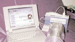
Fully integrated sealing subassemblies, such as a leak-tight magnetically sealed spindle with an integrated motor, have stepped up to meet the increasing demand for sealing and rotation capabilities in a simple computer-controlled, plug-and-play package. Compact size is an increasing concern of many system manufacturers, and a motorized spindle with integrated in-line motor is not much larger than a standard feedthrough. It is considerably smaller than a configuration consisting of a feedthrough, offset gears, and motor.
This type of subsystem combines two key components, a Ferrofluidic seal and a motor. Ferrofluidic sealing relies on a magnetic liquid’s response to an applied magnetic field to seal a rotating shaft. A stationary permanent magnet encircles the rotating shaft, and pole pieces are attached to either side. A series of grooves is machined into either the shaft or pole pieces. The magnetic circuit completed by the stationary pole pieces and the rotating shaft concentrates magnetic flux in the gap between each pole and the shaft, with particular concentration of flux on top of the ridges, or stages, between the machined grooves. A very small volume of ferrofluid applied in the radial gap is strongly attracted to the areas of highest flux density. It forms a series of liquid O-rings on the stages to produce a hermetic seal.
The second key component of the subsystem is a compact, frameless inline brushless dc motor, attached directly to the shaft to drive the spindle. This contrasts with the more commonly used offset belt-driven, geardriven, or shaft-coupled configurations and permits 100% torque transmission — much better than offset drive or flexible couplings — with zero backlash. The integrated motor eliminates the need for gears, belts, mechanical couplings, brackets, and additional framework.
Aside from small size, many vacuum applications require high positioning accuracy. The unit’s precision ball bearings enable high rotational speeds under heavy load conditions with high shaft stiffness and low runout, while speed and position are controlled with an optical encoder and precision controller.
In addition to standard designs, motorized spindles may be customized with several options. For example, direct water-cooling can be added to extend a drive’s capabilities at high temperatures and speeds. They can be designed with solid or hollow shafts and various ball bearings and ferrofluid options. Also, depending on the system’s precision requirements, a variety of encoder and resolver feedback and control circuits may be incorporated.
