This article was updated April 11, 2023. It was originally published March 1, 2000.
To help engineers and design teams get all the performance possible from servo systems, here are some of the more troublesome servo predicaments and how to avoid them.
Controller-to-Servoamp
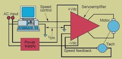
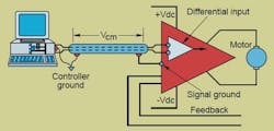
There are often several feet between the controller generating the motion commands and the servoamp. Although it might appear insignificant on a typical schematic like the one above, this separation often produces a ground voltage at the motion controller different from that at the amplifier. Without proper protection, this voltage difference, dubbed “common mode voltage” (Vcm), interferes with the analog signal going from the controller to the amp. This, in turn, leads to erratic servo operation.
It is nearly impossible to eliminate Vcm, but engineers can limit its magnitude to an acceptable level. The first step is to ensure the motion controller and servoamp are grounded together with a good conductor. A machine frame—even if it is a massive hunk of cast iron—isn’t a good conductor. Paint and corrosion can hamper good conduction. And cast iron has relatively high resistance compared to a top-notch conductor like copper. A better approach is to use a shielded cable grounded at both ends to the chassis of each unit.
READ MORE: Get Attuned to Servo-Motor Driver Tuning
There are two types of servoamp inputs. Single-ended inputs are shown in the schematic above. Others offer differential inputs where the operation depends on the voltage between two input terminals rather than the voltage between a terminal and chassis ground, which is highly susceptible to Vcm.
However, even a servo with a differential input (see schematic above) needs a certain level of common mode rejection (CMR) because there will usually be some Vcm. (A unit’s ability to reject Vcm rests in its CMR, usually expressed in dB. Generally, for systems with proper grounding, CMRs of 60 dB or more will do the trick.) Vcm can range from a few millivolts to tens of volts. Therefore, designers add circuits to attenuate the effects of Vcm.
Power Supply
The dc supply rectifies ac to create constant-voltage dc. A pulse-width modulated servoamp chops (modulates) this constant voltage to deliver an adjustable voltage to the servomotor. However, the chopping rate (also called switching frequency) for modern servos usually lies between 15 and 100 kHz. These fast chopping frequencies generate high rates of current rise.
In turn, the fast current increases combined with inductance from leads more than 16 in. long can cause enough of an inductive kick (voltage spike) to create amplifier problems. To solve these, engineers add a 500 mF decoupling capacitor at the amplifier terminals (as shown in the schematic below). This capacitor should be connected as closely as possible to the servoamp’s power semiconductors. So, it should be connected across the amplifier terminals, not the power supply terminals.
It is also imperative that the technicians adhere to the servo manufacturer’s instructions on grounding practices.
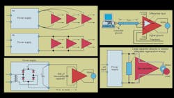
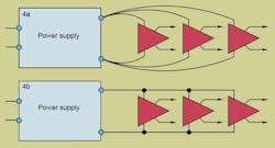
To minimize an amplifier’s interference with another, separate power cables should run to amplifier (as in the upper schematic in the image below) That is because servoamps draw appreciable currents—typically 20 to 50 A. Plus, these currents are a series of fast rising pulses that may create mutual interference between amplifiers (crosstalk). This crosstalk, in turn, often impairs system performance.
READ MORE: Getting the Best Servo Motor
Therefore, daisy-chaining the amplifiers to a common dc bus (as in the lower schematic in the illustration below) exposes downstream amplifiers to all of the power line-voltage disturbances created by upstream amplifiers.
Machine Grounds
To save some wire, it may be tempting to use the machine frame as the return current path for dc servomotors, especially small ones. However, machine frames have substantial resistance, especially where paint and other coatings add to the resistance. Such a high-resistance return increases crosstalk difficulties between amps, which causes erratic machine operation.
Moreover, high currents flowing through a mechanical structure can lead to longer-term, less obvious problems—galvanic action (i.e., rust). This can seriously degrade mechanical joints.
The answer to the problem is to install a separate Vdc return wire from each motor to its amplifier.
Power Supply Droop
By their nature, dc power supplies are unregulated, so the output changes as the input ac voltage and instantaneous load change. Therefore, it is imperative to select a power supply that can send full rated voltage to the amp when ac voltage to the power supply is 15% below nominal rating (a common industry standard for allowable low voltage) and the servo is delivering rated peak torque at full speed. Typically, a servoamp’s peak current is twice its maximum continuous output. This is a worst-case scenario, but it is usually within the components’ ratings.
A good rule-of-thumb is to specify a power supply that can deliver 10% more than the rated voltage under these worst-case conditions. Many engineers have learned from experience that this 10% “headroom” is a wise investment.
Duty-Cycle Syndrome
Of all the “gotchas” engineers encounter when working with servos, none is more frequent than the duty-cycle syndrome. It is commonplace to underestimate the worst-case speed and torque values in applications with wide load variations.
For example, a printed-circuit-board powering a drill undergoes many changes between rapid high-current acceleration and braking. Operations at what might be considered a “normal” running current (which, in this example, is a no-load current) are rare.
READ MORE: Getting the Right Stepper or Servo Motor for Electric Actuators
Because power semiconductors have much shorter thermal time constants than motors, using them calls for servo power supplies and amps with continuous ratings near or equal to the peak rating. Without this seemingly conservative design choice, the solid-state units could fail prematurely.
Coil winders, centrifuges and similar high-inertia loads take a while to reach full speed, so they draw high currents for long periods. Here again, the choice of servo should be guided by the unusual duty cycle’s requirements where torques establish the continuous rating.
Regenerative Braking
Servos can carry out regenerative braking, a method for stopping loads and saving power. This is relatively straightforward because servomotors can operate as a motor to accelerate and run loads or turn into a generator when decelerating. It is then the job of the servosystem to dissipate the newly generated energy.
Battery powered systems such as golf carts, forklifts and automatic guided vehicles are often designed to return the energy harvested from vehicle’s motion to the vehicle’s battery. This extends the equipment’s runtime between recharges.
For servos operating on conventional ac power, the most popular methods for absorbing or dissipating the energy are:
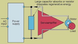
1. Return the energy to a capacitor or resistor connected across the dc bus between the power supply and amp (see schematic above). This is the most common method used in industrial applications.
But engineers must be aware that regenerative energy can be a fire hazard if the amount of returned energy is more than the capacitor or resistor can handle. And if there is too much kinetic energy powering the regenerative braking, the capacitor could overcharge and activate the servoamp’s over-voltage shutdown circuit.
READ MORE: Stepper and Servo Motor Tradeoffs
The motor and load are then no longer under servoamp control and will coast until friction absorbs the kinetic energy. Or, more likely, the motor and load will slam into mechanical stops and possibly damage equipment and cause injuries. Therefore, it is imperative to provide adequate capacity for the capacitor or resistor.
To sidestep these threats and eliminate the need for costly and sophisticated circuitry, drive the load with a low-voltage servomotor. Power the motor from a low-voltage dc supply and control the motor with a high-voltage servoamp.
Also, make sure the reservoir capacitor and rectifier diodes have the same high-voltage rating as the servoamp. For example, operate a 50-V servomotor from a normal 55 to 60-Vdc supply, but use a servoamp and capacitor rated for 180 V. 2. Use a costly regenerative power supply to return energy to the ac power system. For applications with continuous or frequent decelerating requirements this method may be justified.
Barry Friedman was an engineer and founder of Copley Controls Corp. when this originally appeared.
