At a Glance
- The driver is a key factor in determining a motor’s stall performance.
- Temperature can affect the stall torque of brushless DC motors.
- Tolerances on the motor parameters can significantly impact the performance.
Stall torque is the torque available from a motor or other mechanical device when its output speed is 0 rpms. It can also denote the torque load required to cause stalling. Stalled motors are prone to overheating and damages if current flowing under these conditions exceeds the maximum continuous rating. But what parameters affect a brushless DC motor’s stall torque?
Calculating Stall Torque
A brushless DC motor’s stall torque is calculated as:
Neglecting static friction leaves:
where Tstatic friction is static friction due to torque (Nm); Ts is stall torque (Nm); kt is the torque constant (Nm/A); Is is the stall current (A); U is voltage (V); and R is phase-to-phase resistance (Ohms).
Some losses in a brushless DC motor are due to the friction of the bearings, typically ball bearings (Tstatic friction ). This friction depends on the bearing size, preload force, actual loading on the bearing, sealing (if any) and the type and quantity of lubricant. Ball-bearing suppliers provide literature for estimating this starting moment. (In this technical note, we will neglect static friction by assuming stall torque is much higher. But that might not be true for all cases.)
A Tale of Tolerances
Here are the factors that contribute to the tolerance of stall torque based on the first equation.
The torque constant, kt, has a typical tolerance of ±10% caused partly by variation in the permanent magnet’s strength—that is, the variation of the magnet’s remanence. (Remanence is a property of magnets and is the amount of magnetization remaining after a large magnetic field is applied and then removed.) The size of this tolerance depends on the supplier’s manufacturing processes and generally comes to ±2.5%.
The rest of the constant’s tolerance (±7.5%) is due to phase setting. This can be reduced by automating more processes. It could also be lowered a few percentage points by demagnetizing the motor. However, this would lower the torque constant value, which reduces the motor’s torque.
Phase resistance of the motor (Ohms) also affects the standard tolerance, based on the same first equation, and is usually given as ± 8%. This is due to variations in the lengths of the wire while winding it, as well as diameter variation when forming the coil. This is inherent to the manufacturing process.
To calculate the entire uncertainty of the stall torque value, apply a logarithmic function to the first and differentiate it. Then, the absolute uncertainty on the stall torque value becomes:
Input voltage, U, is a constant, so on differentiating the above equation, we get:
Putting in the numbers:
So, the absolute uncertainty on stall torque value is 18%.
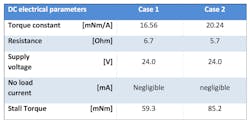
Here’s an examination of a brushless DC motor (Portescap’s 16ECP52-8B-112). Considering the torque constant and resistance value at the limit of their tolerances from the table below, we get torque-speed curves as shown in the graph below the table.
The motor parameters are measured at 24 V, considering the extreme tolerances of the values for resistance and the torque constant. The difference between the stall torques at high and low torque gives the tolerance range. It is equal to (85.2 – 59.3), or 25.9 Nm, and absolute tolerance is given by (25.9/((59.3 + 85.2)/2), or ±18 %
Factors on Stall Torque
Temperature, an environmental factor, can be an extrinsic factor (environmental temperature), an intrinsic factor (joule losses in the coil) or both. That is why phase resistances are always given for a certain temperature, which is typically room temperature (22°C).
Temperature changes the phase-to-phase resistance of the motor which can significantly alter the motor’s performances. Phase resistance, R, depends to a great extent on the temperature as this equation shows:
Where T0 is the temperature at which R0 has been measured; R0 is the phase resistance at temperature T0 ; and γ is the resistivity temperature coefficient of copper (0.0039/°C)
The resistance temperature is thus directly proportional to coil temperature with a linear increase of 0.39 %/°C.
Temperature also affects the motor magnet’s remanence, which then affects the motor’s torque constant. If the working point the magnet is operating at is known, the effects of temperature on remanence can be derived from the magnet’s B/H curves ( characteristic provided by magnet suppliers where B is flux and H is the magnetizing force). With typical magnets in brushless DC motors, assuming the temperature remains below the demagnetization temperature, temperature increases will cause a drop of the torque constant, Kt, of roughly 0.11%/°C.
The controller needed to drive the motor also plays a role. Depending on the type of controller, it directly affects how the motor phase is energized which affects the motor at stall conditions.
There are basically three ways to drive a brushless DC motor:
- Sensorless.
- Conventional control using Hall-effect sensors (6-step drivers).
- Field-oriented control.
The driving method affects motor performances and behavior, such as stall torque, vibrations, smoothness and noise. Here’s a look at how the motor behaves under each of these driving methods:
Sensorless commutation. This method does not require sensors to know the rotor position. There are different techniques of determining the motor’s rotor position without using sensors. The most common is to sense the back EMF (electro motive force) voltage of the non-energized phase of star connected windings. This requires a minimum speed to generate enough voltage, as the back EMF is proportional to motor speed. The back EMF of a motor at stand still is zero. Generally, an open-loop driving sequence starts the motor. Therefore, this type of drive method is not recommended when a motor must operate at stall conditions.
Six-step commutation. Consider a typical brushless DC motor with three phases and one pole pair, which is the easiest case to understand. Such motors can have three Hall sensors shifted by 120 electrical degrees to detect rotor position.
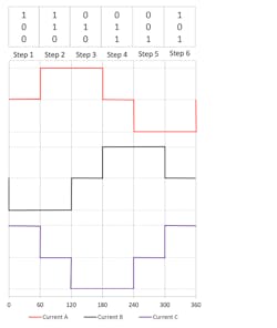
The Hall sensors generate high or low output signals depending on the rotor flux’s direction. Therefore, it generates a six-step logical commutation table over 360 electrical degrees, which is equal to one motor rotation for a one-pole pair motor. Then, the driver energizes the right phases to keep the angle between the stator and rotor fluxes close to 90 deg. to maximize the torque generated. The graph below shows the typical shape of a phase current in each logical state of the three Hall sensors.
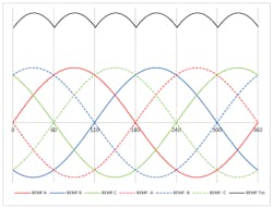
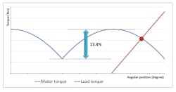
This is a discreet six-step commutation, so the torque will not be constant and will be subject to ripple. The graph below shows the shape of the back EMF (BEMF) over 360 deg. and BEMF’s derived shape. The output torque of the motor would have the same shape.
The available torque will be lower at the moment of theoretical commutation and at its peak (between two commutations). This depends on the angle between the rotor and stator flux (over one-sixth of the entire revolution). This difference between the top and bottom of this ripple is 13.4% of the torque available.
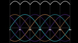
Field-oriented control. This driving method applies sinusoidal current in each of the three phases, as shown below.
Like the six-step driver which needs Hall sensors to know the rotor position, field-oriented control requires high resolution to adjust the current more often depending on rotor position. As a result, the motor’s output torque will be constant regardless of rotor position. This means the motor will operate smoothly, especially at low speed (close to stall condition). The motor will also have up to 5% more torque compared to six-step driver operations.
The tolerance on a brushless DC motor’s electrical parameters significantly affects its stall torque value. It can change by ±18%, depending on the tolerances on the torque constant and resistance values. Other factors, such as temperature variations, which can be linked to the application or the motor, affect the motor’s electrical parameters. Variations due to tolerance and thermal fluctuations are inherent in the real world, and designers must consider them when selecting brushless DC motor for applications.
The driver is a key factor as it affects the motor’s stall performances. When looking for repeatable stall torque values, no matter the rotor position, engineers should consider field-orientated drives instead of the more common six-step drive.
Matthieu Bouat is an application engineer at Portescap.
