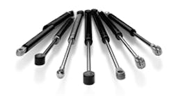
This file type includes high resolution graphics and schematics when applicable.
Proper size and installation extend the life of gas springs and dampers.
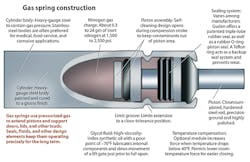
Although the amount of force the springs supply varies with application conditions, it is related to the internal pressure, P1, as well as how the spring is mounted and where. Depending on the rod and tube diameter, springs can come with initial P1 values of 15 to 450 lb.
Designers can choose among accessories and options for their applications. But mounting hardware that accommodates the load’s weight and center of gravity is paramount.
Smart specifying
To specify the right gas spring, designers need to know the weight and center of gravity of the load and apply some basic physics and geometry. The goal is to minimize stroke and maximize gas volume so the output force diminishes slowly over time.Mounting dictates the end connectors and mounting brackets needed. When choosing a connector, make sure it is strong enough to withstand both tensile and compressive loading. And check clearances around the gas spring and mount — workers need easy access to install the components and remove them for maintenance.
The most common connector is a ball-and-socket joint that rotates about the mounting point. Ball joints keep side loads from lids being pushed sideways from reaching the gas springs. They also protect the springs from a torque-induced load if one side of a lid is pushed up or down harder than the other.
What about positioning the spring up or down? The best design keeps the spring shaft pointing down and extending downward through its entire actuation, an orientation referred to as “shaft-down.”
In order cushion the end of the spring’s stroke, the piston must travel through oil at the end of the stroke. Shaft-down orientation ensures the oil is where it needs to be to damp the stroke.
Shaft-down orientation also keeps the shaft and sealing components lubricated with every stroke. This cuts down on seal wear and inhibits corrosion.
Lastly, depending on the application, shaft-down orientation may slow the rate at which gas permeates the seal and escapes. Gas permeation degrades the spring’s force over time and shortens its usable life.
Variations on a spring
Self-locking springs operate automatically. When the spring is fully extended, a locking shroud springs into place, preventing the spring from compressing. Workers can manually release the spring by pressing on the locking shroud, letting the spring compress slowly and predictably.
If the spring is to hold loads at positions other than full extension, perhaps a friction-stop spring is your best option. An adjustment screw lets technicians set the correct level of support. Thereafter, workers can move the locknut to any position along the entire stroke of the spring where it applies “stick-slip” friction to the piston rod.
Adjustable-force springs let workers set the force of the spring before or during installation. These springs are charged to maximum force during manufacture, but a standard tool that comes with them can gradually release pressure to provide the force suited to an application.
Dampers are close cousins to gas springs, but they absorb force instead of supplying it in compression, extension, or both. They are used primarily where heavy loads or doors must be lowered or swung at a constant speed. For example, dampers could prevent a door from slamming shut or swinging wildly open.
Compression dampers operate best in the shaft-up position, which keeps the piston in the oil. Set the stroke so the lid or door is closed before the damper is fully compressed. Dampers mounted shaft-down may operate inconsistently or not at all. However, seal lubrication is not a concern because dampers contain a relatively large amount of oil.
Extension dampers work best when mounted shaft-down and used to cushion end-of-stroke motion. Make sure to use appropriate end fittings — plastic works for lighter loads, but heavier loads require metal fittings.
Double-damped dampers work in compression and extension, but may require a special order. One such type is a self-centering damper. The patented design cushions movement in extension and compression and controls the rate of return from either direction to a neutral position.
Self-centering dampers have an oil-filled inner damping tube wrapped by counteracting torsion springs and encased by a zinc-plated outer tube. Damping speed is controlled by oil passing through an orifice as in other dampers, while the spring returns the unit to the neutral position.
Life prediction
To estimate the life of a gas spring, determine how much force it can lose before no longer meeting the application’s needs. The time it takes to lose this amount of force is considered the life of the spring.
All gas springs lose output force over time, but the rate at which they weaken varies by application and manufacturer. The rate of force loss depends on the size of the support, orientation, number of cycles, ambient temperature, vibration, and application geometry. These factors make it difficult to estimate life accurately without actual testing.
One way to keep gas springs working as long as possible is to keep them within the temperature limits recommended by the manufacturer. Temperature affects the springs’ rate of output force loss and increases their susceptibility to gas loss.
As the temperature of the spring changes, internal pressure changes according to the relationship:
P1/T1 = P2/T2
where P1 = pressure in the gas spring at room temperature, T1; and P2 = pressure at an elevated or reduced temperature, T2. Therefore, as temperature increases, so does internal pressure. And as internal pressure increases, so does output force. For every 18°F change in temperature, output force changes 3.5%.
High or low temperatures can also cause the spring to lose gas charge. At high temperatures, rubber becomes more permeable and gas molecules pass through the seal more quickly. Additionally, some rubber compounds soften at elevated temperatures and lose their ability to seal. Low temperatures compromise sealing by stiffening some rubber compounds.
Multilobe seals and proprietary rubber compounds in some springs let them perform reliably at temperatures ranging from –40 to 176°F.
To help keep your springs working for their predicted life, don’t expose them to temperature extremes any longer than necessary and don’t extend or compress them at these temperatures. Starting out with the strongest spring that handles the application will also keep the springs operating even if some force is lost.
Finally, check springs and dampers periodically a part of planned maintenance to ensure they are working.
|
Authored by: |


