Steady does it: Part 2 of 2
In this installment:
-
Isolation resonance and time-domain response
-
Vibration mitigation functions
-
Disturbance-rejection algorithms, input shaping
In the first part of this series we reviewed how although higher velocities and accelerations are usually required to increase machine throughput, even if a motor can produce enough power to deliver faster operation, an aggressive motion profile does not necessarily yield higher throughput.
Profile duration, the commanded move time, is only half of the equation. The other part is settling time. Settling time is determined by dynamic effects and can significantly increase when a system makes very aggressive moves. The most common vibration mitigation approach is to modify the motion profile by means of trial and error, to keep the entire move and settle duration as short as possible. Often, however, this method is insufficient. Let's explore some more suitable and effective solutions to address the problem.
Frequency domain behavior
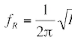
Isolation system dynamic models show that a second-order pole (resonance) and a second-order zero (anti-resonance) are added. Their frequencies are ƒR and ƒA respectively.
Typically, MB >> ML, so the two frequencies are very close. That said, ƒA > ƒR.
Figure 6 (see above, facing page) shows the open-loop Bode plot of a system controlled by a PIV filter. The blue plot is of a system without isolation system dynamics; the red plot shows the effect of isolation system dynamics. Notice the additional resonance and anti-resonance. A phase lead is introduced in the phase: The effect in the frequency domain is not significant, and yet, the effect on time-domain performance can be crucial.
Frame acceleration compensation is successfully implemented with certain equipped motion controllers on systems with passive isolation. Conside a system with 0.0625-µm resolution and a 1-µm settling window. The isolation system in this case does not use air, and its resonance is relatively high, at greater than 10 Hz.
See Figure 7 below. As with active isolation systems, frame acceleration compensation is less effective when the required settling window is a few nanometers or less.
Again, it is impossible to compensate for vibration entirely and settling time is always affected. Systems may also be sensitive to noise resulting from accelerometers, so appropriate filtration should be applied. Increasing servo bandwidth can help, especially on air-table systems where resonance frequency is relatively low — in other words, well inside the bandwidth of the servo.
In many cases, a standard PID or PIV control algorithm is insufficient, and additional high-order filters (and special nonlinear algorithms) further enhance disturbance rejection of the servo.
The example in Figure 8 depicts settling performance in a system where the target move is a few millimeters and the settling window is only 1 nm. Here, a controller with an onboard SIN-COS multiplier enhances output from a 2-µm resolution encoder, to give one example, for a final resolution of 0.49 nm.
Improved settling time
Another example is in Figure 9, which shows the performance of a large gantry stage used for flat-panel display inspection. For this particular setup, total moving stage mass is about 500 kg, and it must be moved at velocity of 500 mm/sec with acceleration of 0.5 g, and then settle into 1-µm window. Basic encoder resolution is 40 ìm and is multiplied by an on-board SIN-COS multiplier for a final resolution of 4.9 nm. The stage is mounted on a massive granite base with vibration frequency of 2.5 Hz. The figure shows the resulting velocity profile, position error, and the in-position bit without and with a disturbance-rejection algorithm — the latter of which shows significant improvement.
Input shaping
Another effective approach is to use special motion profiles designed to avoid excitation of vibrations. Input shaping, a technique developed by Convolve Inc., Armonk, N.Y., is a method for generating motion profiles that minimizes vibrations excitation in moving systems. Software calculates sequences of impulses that do not excite resonant system modes. The impulse sequence is then convolved with target command signals. How is this effective? Because the impulse sequence causes no vibration, the convolution product also causes no vibration.
Input shaping is a feedforward technique that requires no feedback and has no affect on servo stability. In addition, it can handle multiple modes of vibration — so it can be used to eliminate not only isolation system vibration, but other disturbances as well, such as vibrations caused by system cables. It can also help eliminate vibrations unobservable by feedback transducers, but still affecting points of interest.
The disadvantage of using input shaping is that for very low frequencies, it can significantly increase the profile time — by at least half a cycle of the vibration. Preventing the isolation system from vibrating is key to a great design, but only if it does not severely degrade move time. Otherwise, isolation system vibration prevention is suitable wherever its effect on position error is minimized as much as possible.
For more information, email [email protected] or visit acsmotioncontrol.com.
