System modeling: Review of open-source Modelica
Many designs involve multiple engineering domains. For example, hybrid vehicles balance engine performance with emissions limits; UAVs balance thermal limitations on their batteries with cooling-system energy consumption.
Traditional design approaches and software fail to resolve such competing requirements. Nor do they address cost and regulatory constraints — mostly because they force engineers to follow a rigid series of sequential design steps, remain in segregated design teams, and use discrete documents and reference materials that don’t allow global model changes. In contrast, model-based system engineering (MBSE), or system modeling, optimizes even complex designs on the fly. This approach integrates relevant information in one big model to verify designs automatically.
Traditional design work
Many engineering organizations don’t model new designs at all. Instead, they use trial and error and build multiple iterations of hardware prototypes. Sometimes, designs are based on previous versions or artificially narrow sets of parameters. Even when information about a design’s components and their interactions abound, designs may not use it to flesh out the concept. Efforts to predict whether a design will fail take place late in the game, after its basic format is decided.
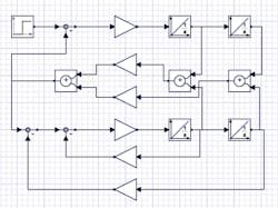
When modeling is used, it often takes the form of traditional signal-flow analysis. First, engineers manually derive differential equations that describe the system. Next, those equations are converted into a block diagram (consisting of adders, integrators, and so on) that specifies how the equations are to be solved. This is causal modeling — profiling designs through cause-effect and input-output relationships. Causal modeling has been around a long time and tools to execute causal modeling are mature. In addition, many engineers are familiar with this approach. Even so, the manual derivation of signal-flow equations is time consuming and error prone. The number of blocks required to implement the equations can grow quickly into the tens of thousands, making models hard to build, understand, and maintain.
Even traditional design software limits flexibility, because most programs only model one engineering domain — just electrical parts, for example — causing problems when an engineer wants to use those submodels in a comprehensive model.
System modeling
System modeling allows integrated simulations of multiple component types in one place, to note physical interactions and design limitations early in product development. In aerospace and automotive, nearly 100% of engineering takes place through system modeling. Other industries rarely conduct design work through system modeling — though that’s changing.
Open-source software called Modelica is one standard for this breed of system-level and production-process development. Its core is a modeling language supported by a standard library of electrical, mechanical, thermal, and fluidic components. They adhere to Modelica Association directives, just as open-source VHDL-AMS (sharing many goals with Modelica) adheres to IEEE guidelines. This makes Modelica models and component libraries portable between software tools, so engineers aren’t stuck using only one vendor.
The standard library consists of nearly 1,300 generic model components and 1,000 functions, and other free and commercial libraries abound. Component models seamlessly combine into system-level models at myriad levels of fidelity. Modelica code also describes library components themselves and lets engineers write new components. Code for existing parts can be inspected, copied, and modified.
There are two ways to build designs in Modelica: Through a graphical diagram or by directly writing source code.
Acausal models
The common way of using Modelica is to graphically build a model in the software by selecting, connecting, and then configuring individual components from a library. Consider the assembly of a double spring-mass-damper system in a suspension model: Connect a step-input signal to a force driver, followed by two sets of sliding masses connected to spring-damper components. The last spring-damper connects to a fixed reference frame.
Diagrams: Equation placeholders
Blackbox component models are models that are partially locked or in inaccessible code. They’re often from suppliers wanting to share a component model with a manufacturer without divulging all its inner workings, or of legacy products built by engineers that have retired. These models are often useless when key details are missing or it’s impossible to figure out what assumptions were made during the original design iteration.
In contrast, Modelica tools can extract the equations from models of components and subsystems for advanced analysis. This extraction isn’t always necessary: The graphical diagram abstracts all underlying mathematics, so dissecting the equations isn’t necessary if an engineer only needs simulation results. In that case, the tool automatically generates the entire set of equations for the system diagram, typically in the form of hybrid differential algebraic equations. It does so by combining the equations from each component with equations derived from component connections.
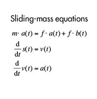
For example, assume we have a mechanical connection between one end of the sliding mass and a spring damper. Displacement of the connected extremities is identical, so their force interactions cancel each other. The software simplifies the equations describing the joint, and compiles and executes generated C code in a differential-equation solver to get simulation results.
Symbolic simplification is crucial. It transforms the set of equations into a solvable set, reduces total equation size, and simplifies output simulation code while maintaining model fidelity. This code executes within Modelica or exports to other tools as Simulink S functions or FMU/FMI, a standard for model exchange.
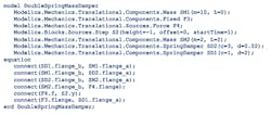
When an engineer needs full access to all of a model’s details, it’s easy to drill down to Modelica’s language level. Consider underlying Modelica code for our double-spring mass-damper system.
Within the code describing this design are declarations such as Modelica.Blocks.Sources.Step, which refers to a Modelica Standard Library component, and Connect statements, which describe how components are linked. Typically, Modelica code includes annotations that specify how model diagrams and component sizes, locations, and connections display in graphical presentations.
Edited by Elisabeth Eitel
About the Author
Laurent Bernardin
Executive Vice President, Research and Development
Laurent Bernardin has worked at Maplesoft since 1999 and led R&D teams to Maple 15 and MapleSim releases. A researcher and an authority in scientific computation, Bernardin is regularly asked to serve at conferences for ISSAC (International Symposium on Symbolic and Algebraic Computing), IAMC (Internet Accessible Mathematical Computations), CASC (Computer Algebra and Scientific Computing), and ACA (Applications of Computer Algebra).
