This article originally posted on May 18, 2016. It was updated on May 31, 2024.
The finite-element, finite-difference and finite-volume methods—FEM, FDM and FVM, respectively—are numerical techniques used in engineering and machine design for solving partial differential equations (PDEs) that govern the behavior of physical systems. They are used for analyzing structural integrity, heat transfer, fluid dynamics and other physical phenomena, with specific usage based on the complexity of geometry, type of analysis required and nature of the system under study.
This article will answer the following frequently asked questions:
- What is the finite-element method?
- What is the finite-diference method?
- What is the finite-volume method?
- What are the advantages and disadvantages of each?
What Are FEM, FDM and FVM?
FEM, FDM and FVM differ from one another in important ways. Understanding these distinctions is key to selecting the method most appropriate for your purposes.
The Finite-Element Method (FEM) Explained
The finite-element method is a computational method that subdivides a CAD model into very small but finite-sized elements of geometrically simple shapes. The collection of all these simple shapes constitutes the so-called finite-element mesh.
LEARN MORE: Register for a simulation software webinar
The next step is to take a system of field equations, mathematically represented by PDEs that describe the physics you are interested in, and formulate these equations for each element. This is handled by approximating the fields within each element as a simple function, such as a linear or quadratic polynomial, with a finite number of degrees of freedom (DOFs). This gives an approximate local description of the physics by a set of simple linear (but sometimes nonlinear) equations. When the contributions from all elements are assembled you end up with a large sparse matrix equation system that can be solved by any of a number of well-known sparse matrix solvers.
READ MORE: Buckling Analysis with FEA
The type of solver used depends on the original physics, since each type of physics gives its unique imprint on the structure of the matrix. To speed things up, this structure is exploited by using a tailored numerical method. A method may be suitable for structural mechanics but not for electromagnetics, and vice versa. Historically, the method was first applied to structural analysis. Since roughly 2006, it has been realized that the finite element method is also suitable for a large class of multi-physics problems.
Understanding the Finite-Difference Method (FDM)
The finite-difference method is the most direct approach to discretizing partial differential equations. You consider a point in space where you take the continuum representation of the equations and replace it with a set of discrete equations, called finite-difference equations. The finite-difference method is typically defined on a regular grid and this fact can be used for very efficient solution methods. The method is therefore not usually used for irregular CAD geometries, but more often for rectangular or block-shaped models.
There is a connection with the finite-element method: Certain formulations of the finite-element method defined on a regular grid are identical to a finite-difference method on the same grid. Regular grids can often be used in meteorological, seismological, and astrophysical simulations, for example.
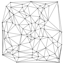
Delaunay triangulations are used to build meshes for space-discretized solvers for the finite-element and finite-volume methods.
An Overview of the Finite-Volume Method (FVM)
The finite-volume method is similar to the finite-element method in that the CAD model is first divided into very small but finite-sized elements of geometrically simple shapes. Apart from this, the finite-volume method is very different from the finite-element method, beginning with the concept of elements, which are instead referred to as cells.
The finite-volume method is based on the fact that many physical laws are conservation laws—what goes into one cell on one side needs to leave the same cell on another side. Following this idea, you end up with a formulation that consists of flux conservation equations defined in an averaged sense over the cells. Historically, this method has been very successful in solving fluid flow problems.
READ MORE: AM Heralds a New Chapter for Fluid Flow Applications | Machine Design
Key Differences Among FEM, FDM and FVM
Each method is quite similar in that it represents a systematic numerical method for solving PDEs. One important difference is the ease of implementation. A common opinion is that the finite-difference method is the easiest to implement and the finite-element method the most difficult. One reason for this may be that the finite-element method requires quite sophisticated mathematics for its formulation.
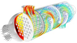
Finite-element analysis of an air-filled shell and tube heat exchanger with water flowing in the inner tubes. Simulation results available from COMSOL Multiphysics software reveal flow velocity, temperature distribution, and pressure within the vessel.
Advantages and Disadvantages
FEM: Benefits and Drawbacks
One reason for the finite element method’s success in multi-physics analysis is that it is a very general method. Solving the resulting equation systems are the same or very similar to well-known and efficient methods used for structural and electromagnetics analysis. Another reason for the method’s success is that it makes it easy to “increase the order of the elements” so that the physics fields can be approximated very accurately. This typically corresponds to locally approximating the physics fields with polynomials of “higher order,” such as second- and third-degree polynomials, or higher. This technique is often critical, for example, in the case of accurate stress analysis.
READ MORE: Spend Your Time Engineering, Not on Differential Equations
If we consider the example of stress analysis, it is quite common that there are important stress concentrations close to some of the corners of a mechanical part. In this case, the finite-element method allows for two different ways of increasing the accuracy of the solution around this corner. One way is to increase the order of the elements, as described earlier. Another method is to locally refine the mesh close to that corner; the element density increases locally. The finer the mesh (i.e., more elements), the more accurate approximation one gets for the stress field around the corner of interest. Both techniques are used in finite-element software and are frequently made automatic from the user’s perspective. This is known as “adaptive mesh refinement.”
Another advantage with the finite-element method, which is particularly important for multi-physics analysis, is that you can combine different kinds of functions that approximate the solution within each element. This is called mixed formulations. This is important, for example, in the case of electromagnetic heating. The physics and mathematics require one type of function for the electromagnetic field and another type of function for heat transfer; they both need to be tightly coupled to get an accurate solution and for the solution to converge. Mixed formulations are straightforward to handle the finite-element method, but difficult or impossible with other methods.
The benefits with both the finite-element method and the finite-volume method are that curved and irregular CAD geometries are handled in a natural way.
However, the mathematics behind the finite-element method is quite advanced and thus the method requires mathematical expertise for its implementation. Implementations of finite-difference and finite-volume methods are comparatively straightforward.
For certain time-dependent simulations, one needs to use so-called explicit solvers for reasons of efficiency. Implementing such solver techniques is more difficult for the finite-element method than for the finite-difference and finite-volume methods. However, this has successfully been commercialized in some cases, such as in crash simulations.
FDM: Pros and Cons
The finite-difference method is defined dimension per dimension; this makes it easy to increase the “element order” to get higher-order accuracy. If you can fit the simulation in a rectangular or box-shaped geometry using a regular grid, efficient implementations are much easier than for finite-element and finite-volume methods. Regular grids are useful for very-large-scale simulations on supercomputers often used in, as mentioned before, meteorological, seismological, and astrophysical simulations.
READ MORE: Math, Models, Motion and More
With the finite-difference method, you may easily run into problems handling curved boundaries for the purpose of defining the boundary conditions. Boundary conditions are needed to truncate the computational domain. They represent communication with the surrounding world, which is the part that you do not want included in your simulation. If one can overcome the boundary-condition problem on curved boundaries, the method gives very efficient and high quality results.
For computations that need high accuracy, the extra effort in making boundary-fitted meshes and the associated complications of such meshes for the implementation may be worth it. Examples include Formula 1 car computational-fluid-dynamic (CFD) simulations and space-shuttle CFD simulations. The finite-difference method is more difficult to use for handling material discontinuities. In addition, it does not lend itself for local grid refinement or anything similar to “adaptive mesh refinement.” This may be needed to resolve local rapid variations in solutions such as around a corner of a complex shape, as described earlier.
FVM: Strengths and Weaknesses
The finite-volume method is a natural choice for CFD problems, since the partial differential equations you have to solve for CFD are conservation laws. However, both finite differences and finite elements can also be used for CFD. Efficient technology for CFD with the finite-element method has become increasingly popular over the last 10 to 15 years. Techniques for CFD with the finite-difference and finite-volume method have been known and used much longer.
The finite-volume method’s strength is that it only needs to do flux evaluation for the cell boundaries. This also holds for nonlinear problems, which makes it extra powerful for robust handling of (nonlinear) conservation laws appearing in transport problems.
The local accuracy of the finite-volume method, such as close to a corner of interest, can be increased by refining the mesh around that corner, similar to the finite-element method. However, the functions that approximate the solution when using the finite-volume method cannot be easily made of higher order. This is a disadvantage of the finite-volume method compared to the finite-element and finite-difference methods.
Applications of Each Method
Practical Applications of FEM
All kinds of structural analysis, heat transfer, chemical engineering, electromagnetics (including electrostatics, magnetostatics, low-frequency electromagnetics, and frequency-domain high-frequency electromagnetic waves), multi-physics, and CFD.
Use Cases for FDM
Weather calculations, astrophysics, seismology, physical realism in computer graphics, and special effects.
FVM in Real-World Scenarios
CFD, heat transfer, and chemical engineering.
Choosing the Right Method
All of these methods are frequently used today in commercial software, as well as in academic environments. The finite-element method is usually most taxing on a computer system, but it depends on the type of analysis.
Bjorn Sjodin is VP of Product Management for COMSOL Inc.
This file type includes high-resolution graphics and schematics when applicable.


