Fused Deposition Modeling (FDM) is an additive manufacturing process in which a machine precisely extrudes melted plastic filament to create a part. Parts are rigid, especially compared to Selective Laser Sintering (SLS), which makes them a great fit for projects with rigidity requirements. Given that the filament has a thickness of 0.010 in. (0.254 mm), some fine features may not resolve properly.
Knowing this, it is important to follow the guidelines set forth in this guide to ensure all features are properly resolved. FDM also requires support material (soluble or break-away) for certain features, so it is important to keep this in consideration when designing parts to allow support structures to be minimized, so as to reduce post-processing and be easily removable.
Note: Designing for FDM is an iterative process. Features will not always print as desired the first time. Realize that producing parts in FDM is a combination of iterating through prototypes and designing for the process, so be sure to have patience and work with the support teams and companies with experience to design parts correctly.
Printing Process
Producing parts in FDM is broken up into three steps: pre-processing, production, and post-processing.
Pre-processing. Printer software slices 3D CAD file into layers. For each slice, the software then converts the data into machine code that determines tool paths for the machine to follow.
Production. An extruder head extrudes melted plastic filament along the tool path layer by layer until the part is completed.
Post-processing. Support material is removed either by dissolving it in water or breaking it off. More custom finishes such as tapping, inserts, and sanding are then applied.
Tolerance
General tolerance:
- ±0.004 in. or ±0.002 in. per inch, whichever is greater
- Build area changes greatly, but some larger industrial printers offer up to 24 × 36 × 36 in.
- Prints in 0.010 in. layers (0.254 mm), or 0.013 in. (0.331 mm) layers for parts over 16 in. (406.4 mm) max dimension
- Minimum feature size at least 0.035 in. (0.889 mm), 0.045 in. (1.143 mm) is safest
Wall Thickness
Wall thickness is limited by the filament size, and features thinner than twice the filament’s thickness usually do not print successfully. Features with only one layer of filament are weak and inaccurate. For supporting structures, walls need to be at least 0.047-0.06 in. (1.2-1.5 mm) thick for best results by allowing filament to fill between layers.
Walls without closed profiles (e.g., lines) are also less resolved compared to those such as circular and closed loops. As a result, thinner, more circular walls are closer to design intent than those with straight walls.
Holes
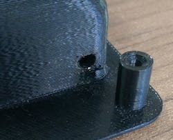
Holes for FDM should be designed with a diameter greater than 0.04 in. (1 mm) to retain a circular shape.
The orientation of holes is very important, and resolution tends to be best when printed parallel to the xy-axis. This is because holes are outlined with concentric circles of filament versus staggered stops between layers.
To increase the accuracy of through holes, we may drill out holes during post-processing.
Text and Small Details
Text and small details are difficult to print in FDM because many small features do not register in the printing process when they are below certain tolerances, such as the filament’s thickness.
Recommended thickness that protruding text must maintain is at least 0.04” (1mm) to register properly. Text must also have a height of at least 0.04” (1mm), but 0.047” - 0.06” (1.2 - 1.5 mm) is recommended to be legible and avoid unexpected errors, which will allow multiple layers of filament to stack on top of each other and reduce the risk of breakage. Cut-out text must also hold these tolerances to resolve properly. Be sure to use regular or larger text fonts, but stay away from more condensed and smaller fonts. All text must also be oriented parallel to the xy-plane for best results, because it will allow multiple layers to stack cleanly and avoid “squished” characters and details.
Gaps
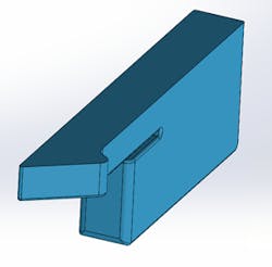
A good tolerance to follow for thin gaps is maintaining a width greater than 0.2 in. (5 mm) to ensure that all support material can be removed. Orienting gaps so that the opening is parallel to the xy-plane is a good way to make sure that parts have resolution. This also reduces the need for support material on that feature.
Tabs
Tabs are very susceptible to breaking in FDM, especially for larger parts. The first thing to do would be to increase the size of the tab as large as possible (size depends on the application and size of the overall part). Orienting tabs parallel to the xy-plane will also increase the strength of the tab and reduce the risk of breakage. Integrating a replaceable tab design is another great way to use tabs in FDM, so that tabs may be printed separately in the best orientation then inserted post-processing.
Fillets
Fillets are a helpful design feature to implement in every additive manufacturing process, especially FDM, in order to reinforce fragile features. Fillets will greatly increase structural rigidity, helping surfaces to build naturally and avoid the need of support material. Support material is required for overhanging surfaces greater than 45 deg. from vertical, so adding a fillet will help the surface gradually grow and continually support itself.
Ribs
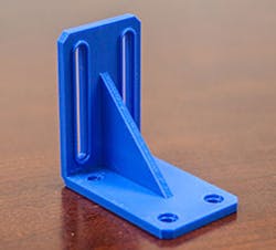
Another great alternative to fillets for increasing the strength of support structures is by adding ribs. This is because ribs distribute the force applied to a structure to a greater surface area. It is important to follow tolerances outlined in the wall thickness section when creating ribs to ensure that they aren’t too thin and either break or don’t register during printing. For this reason, a safe minimum rib thickness to follow is 0.06 in. (1.5 mm) to allow multiple layers of filament inside of each rib.
Infills
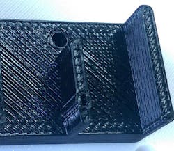
A great way to save money for FDM solid parts is to change the infill type. We have focused on three different infill types: Ultralight, light, solid.
- Consisting of a single cross-hatch pattern throughout the parts, this infill is the most cost-effective for parts that don’t need to be very strong.
- This is the next best option for parts that need to retain some strength. Double cross-hatch patterns throughout the part increases some strength but keeps the price low.
- The standard, strongest option . Material is completely filled throughout the part.
Orientation
Orienting parts in FDM has an enormous impact on its overall strength and appearance, especially for fine and concentric features. Concentric features resolve best when layers print parallel to the xy-axis. Many fine features (e.g., tabs) are stronger when printed parallel to the xy-axis, as well. Designing a part so that fragile and concentric features grow in the same direction will help determine the best orientation for a part to print.
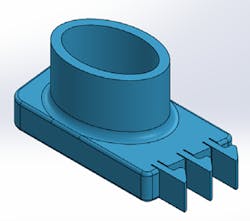
Printing the part shown from the bottom up, vertical tabs are extremely weak and may break off between layers. However, concentric features are more resolved and have no layer stepping. When printing the same part on its side, tabs are much stronger, but concentric features have significant stepping.
Surface Finish
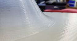
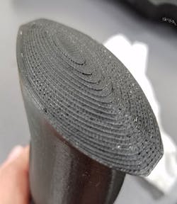
FDM tends to create a rougher and noticeably layered surface finish when compared to other manufacturing processes due to its layer by layer process of extruding plastic filament. This layer “stepping” is especially noticeable for shallow-angled and curved surfaces. Designing parts so that curves and angled-surfaces can grow parallel to the build surface, or increasing angles or curvatures, may reduce this stepping.
Finish and Post-Processing
The following is based on what Xometry offers for FDM parts:
- ABS: strong, affordable, production-grade thermoplastic, many colors
- Ultem: the strongest, most heat resistant plastic available in FDM
- ASA: UV-resistant, affordable, durable plastic, many colors
- Polycarbonate (PC): widely used industrial thermoplastic, offers high tensile and flexural strength
- Nylon: great impact strength, widely used in traditional manufacturing
- PPSF: sterilizable, strong, high-performance plastic
There are currently 16 different colors available in FDM, depending on material, to allow for tremendous customization for any part. In ABS, PC, Ultem, and PPSF materials, you also have the option to sterilize parts to further increase the parts.
In ABS, PC, Ultem, and PPSF materials, you also have the option to sterilize parts to further increase the part’s applications. FDM parts are known for their strength and rigidity, so many mechanical features can be applied to parts without risking structural integrity. Possible features include tapping, inserts, and pins.
Greg Paulsen is director of applications engineering at Xometry.
