In 3D printing (aka additive manufacturing or AM) there are countless ways things can go wrong and only one way they can go right. This is doubly true on the first print of a part, when the engineer finds out if what looked good in the plans holds up as a physical object. Mistakes that are only revealed after 3D printing is done can sink investments in time and capital. Persistent issues can even hamper creativity as they incentivize engineers to build “safe” parts that print successfully, even if they aren’t fully optimized. By solving predictable issues, we can reliably produce more complex parts and let engineers design the best parts for the best performance.
To build confidence in 3D metal printing, we need to increase the accuracy of first-article prints. The first step toward doing this is to ensure system stability by monitoring and controlling powder-bed environmental conditions and those of the optics. However, even this isn’t always enough to create a part that meets dimensional specifications.
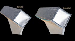
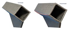
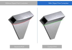
Two sample parts of the same hollow rectangular prism are 3D printed horizontally. The image on the right shows out-of-plane deformation (red line), common on 3D-printed parts due to residual stress buildup during printing. On the left, an accurately printed part was corrected by printing-simulation software that pre-deforms the design before manufacturing to account for printing stress. (Courtesy: Velo3D)
One reason for this is the large amount of residual stress induced in the part by the repeated heating/cooling from the laser beam during the layer-by-layer melting. This stress can result in the part distorting and warping as it prints. As an industry, we add supports to hold parts in place and then heat-treat after the build to try to minimize these distortions. Alternatively, we turn to tribal knowledge to modify the geometry sent to the printer to address part deformation ahead of time.
To move efficiently to finished production, we will need more advanced solutions. The good news is that other industries have figured out some of these challenges and laid important groundwork for very specific process-solutions in AM. Advances in simulation now let us calculate the stresses during a print and predict deformation.
Let’s walk through some of the issues related to part deformation and see how custom simulation programs can help improve first-print yields.
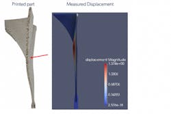
On the left is a printed hyperbolic paraboloid-type shape showcasing in-plane deformation. On the right are the expected structural displacements if printed as is.
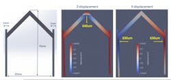
One solution is advanced printing simulation software that anticipates many of the deformations that will arise during the build due to the part’s structure. One example depicted below appears deceptively simple. It has two parallel “walls” connected by a 45-deg. pitched “roof”. This part will move and distort dramatically mid-build as the roof pushes the walls outward and its peak sinks.
The machine-specific software can simulate the build directly from a CAD file and identify areas where the part will change shape during the print. The engineer can then adjust the part or use the built-in deformation correction capability. This automatically adjusts the print plan so that the stresses incurred during printing distort it into the correct shape.
These images show an example of simple part dimensions (left) and specialized simulations (right) predicting deformation along the Z and X axes.
A roof structure printed directly from the CAD model (left) is next to one made with object pre-print correction. The OPC corrected geometry has significantly better dimensional accuracy.
These images show a printed object before and after Object Pre-print Correction in Flow Software from Velo3D. A simulation engine analyzes the design, predicts deformation in the print, and applies counter-deformation to the part so that the print comes out right on the first build. Also predicted are part risks and failures, which validate the execution feasibility of the print prior to starting the build process.
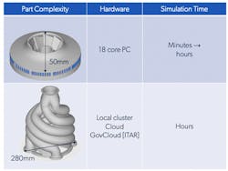
Supercomputers are not needed to run the simpler aspects of such calculations, thanks to the simulation software’s efficiency. As the part gets larger and more complex, however, the processing power required increases and simulations can be run in the cloud. This last scenario brings down even the biggest jobs to a few hours and, best of all, improves the likelihood of a part printing as planned.
3D-printed part complexity affects hardware requirements and run times. The image above on the left is a sample shrouded impeller as might be employed for aerospace, oil & gas, or general industrial applications. At the lower left is a sample exhaust manifold concept.
The vicious cycle of prototyping cost manufacturers time and money. These issues can continue indefinitely, because basic challenges have to be solved before the build can move forward. Even worse, these events can cascade as larger projects get backed up due to the troublesome part—creating significant loss-of-opportunity costs. By innovating around the most common problems, advanced AM systems head off the thorniest, costliest conditions before they happen. Nothing beats getting it right the first time.
Gregory Brown Ph.D., is VP of Process Engineering, Velo3D. For more information on 3D printing, call (408) 610-3915 or visit www.velo3d.com.
