New techniques to predict machine vibration
All rotating and reciprocating equipment generates vibration as a byproduct. These cause gearbox rattling, driveshaft breakdowns, shaft bends, driver discomfort, and noise. In contrast, less vibration makes for better reliability, quieter operation, and higher enduser satisfaction with a design. It’s relatively difficult to predict these vibrations, partly because they change with the machine’s phase of operation, and a given machine exhibits unique vibrations upon startup, shutdown, and normal continuous operation.
Often, the only evidence of problematic vibration is gear noise or coupling wear. These early indicators of vibration can eventually develop into high-amplitude vibrations that cause gear wear, gear-tooth failures, and even broken shafts. So to ensure system reliability, designers should analyze and evaluate the torsional response characteristics on the rotating subsystems on their machines.
One of the most thorough approaches is to model the machine using a lumped-mass (or lumped parameter) representation, combined with experimental measurements. Lumped-mass models (or lumped-parameter systems) are often used as opposed to distributed-parameter models when the physical object has dimensions that are small relative to the direction of vibration. Lumped-mass models are idealized systems of rigid masses jointed by massless springs and dampers. Compared to distributed-parameter systems, lumped models are simpler and allow for faster simulation. The number of degree-of-freedom, which is defined by the number of masses-springs-dampers, of a lumped model can be increased to improve the accuracy of the model. A long shaft with torsional vibration or bending is a good candidate for lumped-parameter analysis.
Using advanced symbolic for model simplification/order reduction and numeric techniques for solving the equations with simulation software, designers can diagnose and solve myriad vibration issues.
Root causes of failure
In industrial environments, the most common cause of machine breakdowns is bearing failure. Mechanical problems that can damage bearings but can’t be seen directly include unbalance, misalignment, mechanical looseness, bent shafts, resonance excitation, as well as problems with belts, gears, aerodynamics, and electrical connections.
Consider a passenger-vehicle powertrain. Most vibration on the driveline comes from power-input fluctuations, particularly when a combustion engine provides the mechanical power. Other vibrations on automobile drivelines come from:
- Forced responses of periodic excitation from fluctuating engine torque
- Transient responses of the driveline to impulses from gear shifting
- Clutch-judder phenomena during clutch engagement
- Excitation of the driveline’s natural frequencies to avoid coincidence of engine-torque harmonics
Such a machine’s vibrations also couple with movements of the machine structure. For example, a vehicle in heavy urban traffic must frequently stop and start. During acceleration, rotary vibrations in the drivetrain temporarily couple with the car’s vertical and horizontal motions. The forces associated with these motion inputs complicate the vibration analysis of the design’s mechanical structures.
Two techniques for modeling vibration: FEA + lumped-mass models
In general, there are two approaches to analyze these vibrations. The first technique is FEA, which models mechanical structures as thousands of discretized and idealized elements. A designer then analyzes the relationships between the elements to construct the mass, stiffness, and damping matrices and determine the natural mode shapes and frequencies of the structure during vibrations. Before FEA-based analysis, though, a meshing technique discretizes the object into thousands of basic elements. This approach has advantages for objects having complex geometries. However, analysis of a machine’s vibrations using FEA-based elements means the software must solve huge systems of thousands of linear equations. That makes vibration analysis with FEA time consuming and expensive.
An alternative for analyzing machine vibrations, particularly on relatively simple rotary shafts and drivetrains, is to use lumped-mass models and experimental measurements. For example, to model a long shaft with multiple diameters and properties, the designer uses the software to divide the shaft into many segments defined by masses and inertias, springs, and damper components. The nonlinearity of the spring stiffness and damping incorporates easily using a mathematical representation or a lookup table based on experimental data. Then the designer can add gears, clutches, and other components (including backlash values) to complete the model.
The source of excitation is one of the most important parts of a lumped model. Later in this article, we’ll explore two application examples: In one, the source is an internal-combustion engine that induces vibrations via reciprocating piston and slider-crank mechanism movements. In another, it’s a turning ship propeller cutting through ice and water.
The first step is to use the software to create a 1D physical model of the design — focusing on the machine’s mechanical linkages. The model consists of springs, dampers, masses, and rotational inertias, as well as force and moment components for either the torsional or translational domain. All other motions are ignored to keep the model simple.
Next, use table-lookup components to incorporate experimental data into model elements, which define behavior in terms of nonlinear springs and dampers. Some software also integrates custom-component data on spring forces, damping forces, and moments from Excel spreadsheets. That lets designers edit component equations to fit the application.
Once a lumped model with vibration excitation source is set up, the software executes vibration analysis numerically in both time and frequency domains (based on the simulation results) or analytically (based on the mass and stiffness matrices extracted from the model).
Engine excitation model
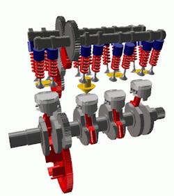
Consider the internal-combustion engine. Its predominant vibration source is variations in gas-pressure torque, related to the cylinder gas pressure by the slider-crank geometry:
where Tg = engine gas-torque, Nm; Pg= cylinder gas pressure, MPa; A = lateral piston area, mm2; R = radius of the crank shaft, mm; and φ = rotation of the crank shaft, degrees The engine produces gas pressure for torque pulses that repeat after every complete working cycle. A four-stroke, single-acting engine has an interval of 4π or two crankshaft revolutions. A two-stroke engine has an interval of 2π. Due to this harmonic nature, the gas torque is usually represented as a Fourier series:
where ho = maximum number of required harmonic orders; and To= constant function of the cylinder firing angle, crankshaft radius, nominal power, and other constants.
Notice how this gas-torque equation consists of a steady part, To, that doesn’t excite vibration and a fluctuating part that does.
In engine-vibration theory, the harmonic order is the number of excitations during one crankshaft revolution. The fourth order repeats twice in a four-stroke engine, so the harmonic orders are half multiples — ½, 1, and 3/2. The fourth order repeats four times each revolution in a two-stroke engine, so there are no half-orders and the orders are integer multiples.
In the above gas-torque equation, the sine and cosine terms represent the harmonic orders and half-orders. The parameter ho is the maximum number of required harmonic orders, typically with a value from 8 to 12.
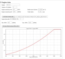
In some software, designers can define the harmonic orders for the engine (including half-orders for four-stroke engines) through symbolic equations using Modelica or custom component code. First determine the amplitudes of the sine and cosine terms for each harmonic order in the series from simulation or experimental data. Then enter these amplitudes into a model as 2D lookup tables (to represent the strength of all the harmonic orders over a range of the engine’s mean effective pressure).
For a four-cylinder engine, the designer must determine gas pressure for different speeds and load conditions. The usual practice is to test several engine prototypes on a test bed with a pressure transducer fixed inside the combustion chamber. The transducer measures gas torque in the chamber and integrates that collected data into the lumped model.
Excitation also varies with the rotational shaft speed, which directly influences the vibrational frequency, so the designer must analyze the machine vibrations over a range of engine rpm.
Likewise, to model a multicylinder engine, assume that all the cylinders have the same outputs, so the gas torque is the same for all of them. The only caveat is that there’s a phase difference between the fluctuating torques in the cylinders. (Any more detail about the model is beyond the scope of this article.)
Some software has vibration-analysis templates to let designers execute all vibration analysis in one software environment. It lets designers linearize nonlinear models for control design or modal analysis. For example, the designer can extract any driveline model’s dynamic equations in symbolic form, extract stiffness and damping matrices, and plot the mode shapes. That way, plots can reveal machine behaviors so designers can remedy the weakest parts.
Torsional vibration in a ship driveline
Consider a large ship moved by a propeller through water. The driveline that powers the propeller needs torsional-vibration analysis. In fact, this is a good application to explore because it has driveline elements common to myriad machines.
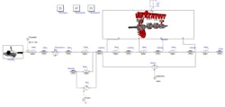
The propeller-driveline model consists of a four-cylinder, four-stroke internal-combustion engine, a propeller that produces the thrust to push the ship forward, and shaft sections modeled as inertia components with spring-stiffness and damping properties. Assume that the propeller and engine connect through a simple reduction-gear transmission. Assume that there’s a pump at one end of the shaft. Also assume that there’s a flywheel attached to cylinder one for damping vibrations and smoothing output motion by leveraging Newton’s first law.
The two most significant sources of vibration in this case are the engine and the propeller. Therefore, we need highly detailed models for these components.
The driveline is structurally simple because there are no translational parts, so a 1D lumped-mass model is sufficient. Both engine and propeller subsystem models contain formulations that account for the fluctuation torques that excite vibrations.
To evaluate the engine design, load the cylinder gas-excitation torque data generated from real experiments into the simulation software using 2D lookup tables. Then model the propeller torque as a second-order sinusoidal function that describes the vibration as a function of rotational speed and the number of propeller blades.
Eigenvalue and order analysis
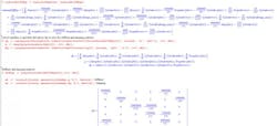
Software built on symbolic mathematical computation lets designers extract dynamic equations for entire models or individual components. One command from within the software extracts differential equations to describe the driveline. Another command yields a stiffness matrix with the model’s eigenvalues and eigenvectors (natural frequencies) and mode shapes. Where available, linearization templates yield stiffness and damping coefficient matrices for nonlinear systems.
A more visual and common technique for investigating vibrations and sounds from rotating machines is order analysis. Its strength is that it generates a plot that clearly shows discrete peaks in vibration signals for excited machine subsystems. Designers use order analysis to test devices ranging from gearmotors to gas turbines and even dental tools.
How does it work? Like other techniques, order analysis tracks how vibration peaks when an excitation frequency coincides with a machine natural frequency. It’s unique in that it identifies critical speeds and then normalizes their orders (multiples or harmonics), so frequency bandwidths of individual harmonics don’t spread on the plot or overlap. Because the technique plots amplitude against order and not frequency, designers can quickly identify vibrations over varying speeds.
Returning to our example engine application, excitation frequencies change with engine speed, so several excitation conditions arise over the operating speed range. But discrete vibration-engine speed relationships aren’t always obvious on plots generated by standard dynamic signal analysis such as Fast Fourier Transform — particularly when a machine sweeps through a range of rotational speeds. Therefore, order analysis is a better choice to identify all the signal components that the rotating machine generates.
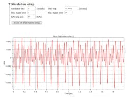
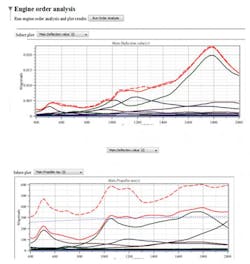
Consider order analysis on an engine run-up test. Here, software can plot the vibration magnitudes for shear stress, vibratory torque, and power loss at each harmonic order.
For designers, this information is crucial because it helps them identify individual components and how each contributes to (or degrades) overall performance. For example, with just a quick inspection of an order-analysis plot, an engineer can tell which particular gear or driveline component on a machine causes the most vibration at a given rpm.
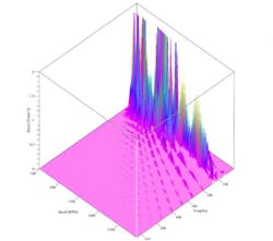
Another way to use order analysis is to set the software to generate a waterfall diagram. These typically plot the spectrum of orders at a range of rpms and frequencies against a Z axis showing shear stress at key locations. That way, the waterfall diagram lets designers examine the resonance for each order and rpm. Then, if specific orders look like they’re the most problematic, the designer can examine them and ignore the others.
Resources: Maplesoft page on vibration analysis
