With increased confidence in 3D printing, more design engineers are looking to see where new processes could add a competitive edge. While cost associated with 3D printing is reducing, metal printing could still be a large capital expense. Additionally, 3D printing metal still has many variables and controls that inhibit the process from being user-friendly. With a relatively large investment and the need for knowledge, design engineers might shy from printing in metal.
Some initial benefits 3D printing metal or plastic is the ability to generate geometries not possible with other processes. Additionally, interior channels, combining multiple parts into one, optimizing geometries, improving functionality, reduced tooling, and increasing flexibility are some of the thoughts that may be in a design engineer’s mind. But there are also other indirect benefits of 3D printing to consider.
Long lead times: If downtime costs are extremely high because of lead times on parts or tooling, 3D printing could offer a solution. Specifically for tooling, design engineers can eliminate or reduce time by printing the part directly, or printing the tooling.
High inventory costs: 3D printing allows for on-demand production, reducing the need for inventory.
Sole-sourced from suppliers: By qualifying parts for 3D printing, companies will no longer be as reliant on suppliers.
Remote locations: when remote locations restrict delivery of parts, on-site 3D printing can eliminate delivery times.
High import/export costs: On-site 3D printing production also eliminates high import/export cost.
With a focus on metal printing design keeping cost in mind is important. It is important engineers understand what’s the difference between metal 3D printing processes? Different processes might have different abilities, material options, and even variable material properties. Design could great increase or decrease post-processing time and cost. Specifically with the powder bed processes, post-processing can easily take more time and cost than the printing process. The following will look at some of the benefits and limitations to keep in mind when considering designing with direct energy metal powder bed 3D printing.
Design Considerations
It is important to understand 3D printing is an evolving industry. The machines from five years ago might not have the same capabilities as newer equipment. Guides from years ago, or from different brands can have various design parameters. For example, if an expert says support structures are needed for an overhang of 30 deg. while another expert says it doesn’t, this conflict could be due to the age or type of equipment, or even the type of material that is being used. If design limitations or possibilities change, make sure you ask why.
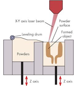
It is important to understand that there is a difference between sintering and melting. Sintering normally uses a lower power laser. The energy is enough to compact, but not melt the powder. This might also be a term that is lost in hype and marketing, so it is important to understand whether a company offers sintering, melting, or both.
Some aspects of design will not change when moving into 3D printing design. Engineering fundamentals such as stress consecrations exist in the design and will not change based on process. If a part breaks don’t assume it was the 3D printing process that was the problem. There are differences between designing for metal 3D printing than casting or CNC machining. For example, subtractive processes tend to have sharp corners where 3D printing would benefit from progressive build-up such as fillets or chamfers on edges or corners. Progressive build ups also relate to reducing downward facing surfaces and support structures where possible. These changes to design will be covered in more detail later.
More specific considerations in 3D design starts with CAD software. Just like traditional design, designing and testing parts in the software first can save a lot of time and money. This can be more important when moving into metal 3D printing.
Do as much planning digitally to prevent failures. Especially when printing metal as it is more expensive than other processes. Failed prints waste the powder on the failed part. Additionally, depending on the material, the unsolidified powder will need to be replaced or recycled which involves filtering it and adding some virgin content to ensure materials properties are maintained. Design engineers need to understand the cost and loss of time associated with failed prints. Setting up a process to check and double check CAD files and code on a new print is worth the additional time.
Bridging the Gap in Software
It is important to find software that identifies not only the design but offers features specifically for 3D printing to fill the gap between designing and printing. Anyone who has experience with programs like MasterCam understands moving from a CAD program to generating g-code for a CNC machine can have errors and even crash a machine.
An eBook titled Metal Additive Manufacturing Software offers considerations for 3D printing. The following is an excerpt from the guide.
- Import: Use the 3D CAD model either as mesh or solid and perform printability checks. If needed, the model can be adjusted or healed to make it printable.
- Position & Modify: Orient the part on the print tray for best results based on criteria like printing time, surface quality, material consumption, and more. Modifications required for the manufacturing process such as adding material for post-printing machinery operations can be applied to the model.
- Optimize Structure: Add volume and surface lattice to reduce weight or to enhance the functional properties of the part.
- Supports: Set support structures required to eliminate deformation and build failures.
- Simulate and Analyze: Software that is able to simulate the entire build process will be able to predict failures and minimize the number of print try-outs.
Additionally, there are in-line inspection programs, such as the one developed by Sigma Labs, which can determine if a print has failed before it’s finished printing. Having this knowledge saves a machine hours of operational time and from printing thousands of layers of materials on top of a flaw which will render the part scrap. In-line monitoring can use previous knowledge of failure variable—temperature, speeds, laser diameter, melt diameter—to determine if a flaw occurred in real-time to stop operations and save any more time of material from being wasted on a part that will fail.
Post-processing and Angles
There are a lot of experts that talking about reduced post-processing in design by altering angles, but another consideration The Definitive Guide to Direct Metal Printing mentions is the difference of upward and downward facing surfaces. Downfacing surfaces have a higher roughness compared to upward facing surfaces. Reducing post-processing with self-supporting downward angles will generally decrease the surface quality of the downward facing geometries. This again will depend on the type of printer, process, and material.
For example, titanium alloys could have a self-supporting angle of 40 to 45 deg. while steel, CoCr, and aluminum-alloys could be between 50 and 55 deg. If design engineers don’t understand how these angle could change the downward facing surfaces, it will be important to do some test pieces or experiment to ensure part quality. Changing the part orientation can help reduce support structures and downward facing surface roughness, but there is more to consider.
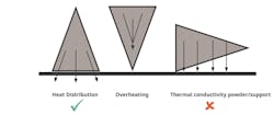
Proper orientation can reduce support structures that can reduce post-processing and surface roughness. Additionally, when oriented properly a part can reduce thermal stresses by transferring heat to the build plate or the machine itself. (Credit: 3D Systems)
Orientation could reduce supports and downward-facing surface roughness, but it could create problems with holes, threads, and thermal stresses in the part. Additionally, it is important to consider the available build space a machine must work within. The Definitive Guide to Direct Metal Printing explains how orientation and support can help produce a successful print when considering these concerns.
Thermal Stress
A higher material melt temperature (e.g., titanium and stainless steel generally require more energy, creates a process that rapidly heats a small local area. A high temperature lacking thermal mass leads to rapid heating and cooling cycles as parts are built layer by layer. Before moving on, it is important to understand this article is addressing melting, not sintering. Sintering normally uses a lower power laser. The energy is enough to compact, but not melt the powder. This might also be a term that is lost in hype and marketing, so it is important to understand whether a company offers sintering, melting, or both.
In the case of tall, slender geometries that might be connected, like a bridge, it is possible the connecting layer could shrink and deform the legs. Furthermore, the layers built on top of a layer that has experienced shrinkage will be built to the original size and create an overhanging ridge. To correct this, the part could be built with the large section first. (Credit: 3D Systems)
Metal sintering, also called direct metal laser sintering (DMLS), can reduce internal stresses cause by excessive heat. Without the thermal stresses caused by some of the other processes, including 3D printing and traditional, DMLS parts can operate in the aerospace and automotive industry for applications that may see high stresses. DMLS can also eliminate post-thermal processing such as annealing.
When looking at melting processes and materials with high melt temperatures, thermal stresses can cause warping and shrinkage. Orienting a part to reduce large surface areas that are parallel with the build direction (the X, Y plane) can help dissipate heat before the next layer is added. Support materials can help hold geometries in place. However, it is important to remember the stress is in the part so do not removed supports until after stresses are relieved. Removing supports before thermal stress are relieved will cause the part to warp.
A good example of a part with multiple challenges might be a large geometry, say a rectangle, with multiple tall, thin, leg-like connections. Building the part upside down or starting with the rectangle with the legs extending up will address multiple concerns. One, the larger geometry of the rectangle can use the build plate like a heat sink to reduce thermal stress.
Two, orienting the part this way eliminates the support structure to carry the areas between the legs. The powder bed processes fill in blank space with unsolidified powder. However, it is possible to have areas built on unsolidified powder with no geometry or support underneath to fall out of tolerance. Printing parts with bridges or cantilevered geometry still needs support. Changing the orientation can eliminate the need for this support structure and downward-facing area concerns.
Three, chamfers and fillets will also help reduce thermal stresses. Long, thin structures such as the legs or upright mentioned previously can shift in the build space between layers. Adding or elongating chamfers, fillets, or adding supports will help maintain tolerances when building long thin geometries in the Z axis.
Orienting parts might seem simple, but with thermal stresses, support-structures, and other concerns that come with 3D printing, design engineers need to know how a machine will behave with different materials and new geometries. This is where having software that can simulate the printing process and considers material properties and thermal stresses will reduce headaches for design engineers and promote successful prints. With or without CAD features, remember, thermal stress is proportionate to the melted surface area and the temperature drop during solidification. To mitigate this:
- Reduce area to be melted per layer
- Ensure longest direction of parst along Z-axis
- High number of small sections is better than one big section
- Make sure you have good heat transfer to the baseplate and machine
The better the heat is transferred, the less a part will warp. Knowing more about heat stress and transfer is important. If thermals stress can be reduced in the design, orientation for thermal stresses might not be a concern. This offers more flexibility to address other orientation concerns.
For example, if a part has holes or threads that are perpendicular to the build direction supports might need to be used. This will decrease post-processing. While holes under 8 mm in diameter might be self-supporting, holes perpendicular to the build direction will be self-supporting no matter the size. This also helps ensure circular holes and concentricity.
Orientation can be difficult as the needs for supports, thermal stresses, holes, and threads might want to alter the orientation differently. If you are looking to purchase equipment or a service provider, different processes, materials, software, or even print models might eliminate or reduce some of these concerns. This is just some of the reasons why expertise in a variety of materials and printers can offer a large competitive edge in manufacturing. By understanding the capabilities of the materials and printer used to process parts, designers will be able to start with a set of design specs that can greatly improve downstream time and cost.


