Recognizing the limits of traditional CAD for creating and controlling highly complex designs, a new effort has been launched to combine 3D modeling, simulation, and manufacturing processes into one computational modeling environment managed through a strong, custom visual programming interface.
The goal is to enable industry to quickly and intelligently automate every aspect of the journey from modeling to manufacturing. This will help ensure that teams follow best practices, strengthen their collaboration, and apply greater innovation to next-generation products.
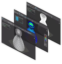
An example of an integrated environment with shape, engineering analysis, and manufacturing toolpath outputs. Changes in an upstream parameter instantly result in updated manufacturing data. (Courtesy: nTopology)
The Important Role of Visual Programming
Visual programming is one medium of computational modeling. It removes the immense complexities that come with the territory of software engineering while allowing engagement with the underlying technology of CAD platforms in algorithmic ways. One key advantage of this type of programming is that it affords users the ability to automate and modularize complicated modeling tasks.
Although visual programs provide benefits for those desiring more automation than CAD tools allow, they have many limitations. They are general purpose, have complicated user-facing data-structures involving a steep learning curve, are only compatible and built for mesh and B-rep geometries and, lastly, require a thorough understanding of the topological structures of each.
Also, as mesh and BRep geometries become larger and more complex, so does managing change. Users end up entangled in managing the data-structures required to construct the topology of the meshes and BRep of their system, rather than focusing on their design goals.
A scalable computational modeling environment requires a robust, user-friendly visual programming interface that acts as a conduit to an equally powerful geometry kernel.
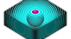
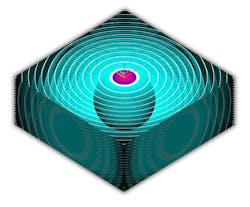
Distance field information is stored in models and can be used for complex model edits such as booleaning, offsetting, and filleting. (Courtesy: nTopology)
Computational Modeling
Computational modeling is the process of developing and deploying algorithms to automate and execute design, simulation, and manufacturing workflows. It is a means of achieving a solution space of results based on user-prescribed relationships among geometry constraints, engineering data, and manufacturing requirements.
Imagine a lattice with a constant thickness occupying a volume. Now imagine that same lattice but with a variable thickness to better accommodate externally applied forces. Now let’s change the volume, the lattice type, and the loads. In a traditional solid modeling sense, this would be a daunting and painful task to accomplish. With computational modeling in place, it is as easy as changing a few parameters once the logic is set.
With a math-based approach, the modeling, simulation, and manufacturing processes are combined into a single, integrated, uniform computational modeling environment managed through a custom visual programming interface. This serves to untangle complexity at the user level. The outcome enables engineering teams to intelligently automate every aspect of the product development journey. When disciplinary silos are bridged by software improvements, then collaboration, speed, quality, and innovation naturally flow.
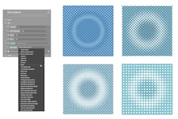
Four different lattice structures responding to a distance-based modifier via variable strut thickness, all derived from the same notebook. This example demonstrates how users can make major changes to their design while simultaneously respecting the constraints. (Courtesy: nTopology)
Deploying “Blocks” and “Notebooks”
Developing an algorithm may sound a bit challenging, but this visual programming environment is easy to use, devoid of complicated data-structures, and augmented by implicit modeling technology. With the “block” system inside the platform, teams are now programming without learning a new language. The visual program consists of a dictionary of blocks, each containing a discrete function with inputs and outputs (with outputs serving as new inputs), which aggregate to form what we call a “notebook”.
At first glance, notebooks may appear similar to the tree structure most commonly found in feature-based CAD programs, or as an alternative to canvas-based style parametric visual programming.
Under the hood, notebooks are essentially large mathematical super-equations that output positive and negative values in all three dimensions. These values make up our “field”, and the bounds of our chosen geometry reside at the location of all the values that equal zero. Values internal to the geometry are negative and values external are positive. Values increase positively and decrease negatively as we move farther away from the bounds.
These ever-present values are used to execute modeling operations such as booleaning, offsetting, and filleting due to the fact that implicits are not defined or constrained by topology. This process of defining geometry through mathematical equations is called implicit modeling. It is modeling in the purest sense.
With notebooks, implicits are enhanced through synthesizing simulation and manufacturing data to create field-driven designs.
In the lattice example, the computational modeling platform allows users to populate a part to optimize with a lattice, run structural analysis simulations, and use the resulting simulation data to optimize and fine-tune the lattice further in one connected environment. Modifying the part or swapping the lattice structure for another is just a matter of changing a couple of values in the notebook.
The benefit is that this same notebook can seamlessly be used across many different scenarios. It is a simple experience for the end-user, and they need not learn a new syntax in the process. The notebook concept doesn’t just enable teams to automate, capture; and modularize custom workflows; it allows engineers to increase product functionality, save time, and avoid errors.
Engaging with implicits and fields iteratively through user-defined algorithms allows engineers to evolve and execute the type of complex designs and stress requirements typical in additive manufacturing and other advanced manufacturing projects.
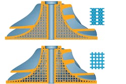
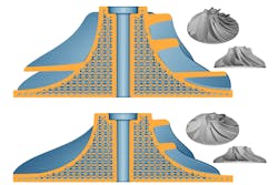
Various lattice structures can be integrated and tested for lightweighting and structural optimization. In the top example, two different lattice structures are applied to the same impeller. In the bottom example, the same lattice structure is applied to two different impellers. (Courtesy: nTopology)
A Bottom-Up Approach
Computational modeling is a bottom-up approach that is an efficient, intelligent, and scalable means of solving the most challenging engineering problems. Its single, uniform environment improves collaboration between teams and better ensures that learned knowledge is preserved and passed along for future products.
As the demands of advanced manufacturing continue to evolve and product complexity increases, the blocks and notebooks built into a computational modeling platform will accommodate those changes and continue to improve product performance and economy going forward.
Andrew Reitz is a product designer for nTopology.
