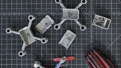
Drones are changing the way we see the world—literally. From YouTubers who fly these tiny vehicles to show the world stunning views of their city, to farmers monitoring their crops from a bird’s-eye perspective, drones have made a huge impact in our personal and professional lives.
As an industrial designer, I’m always fascinated by the way things work, and drones are no exception. That’s why I decided to reverse engineer and rebuild one. I dissected the components involved, designed the new body in CAD, and used a 3D printer to bring my final design to life. There was plenty of trial and error, of course, but the project sharpened my design and engineering skills while helping me to better understand the design decisions that go into building an actual drone.
Step 1: Dissect and Evaluate the Components
I began the reverse engineering process by carefully disassembling the original drone to expose all of the individual parts. By taking the time to learn how each part interacted with the others, I was able to determine the constraints of my redesign.
For this particular project, I had to consider the fixed distance between the motors. The weight of my new design needed to be close to that of the original drone as well. These aspects of the design couldn’t change, but I could experiment with other parts: the location of the ports, the positioning of the boards, the wire routing, and the overall structure and durability.
Taking the time to dissect and really understand the original drone proved to be one of the most important steps in the entire process. Once I determined how I would actually recreate my own drone, it was time to take my ideas from my sketchbook to my computer.
An early study for fitting motors and boards in a tiny space.
Step 2: Create Blind Solids Based on Components in CAD
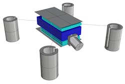
Using the information I learned while taking apart the drone, I took measurements to design blind solids in CAD, which acted as placeholders for the fixed constraints in my new design. Calipers were a must for this step. Used to measure the distance between opposite sides of an item, calipers are an ideal tool when working on small-scale projects. My tip for using them: Try to get your dimensions down to at least 100 micrometers.
Blind solids are great placeholders to design around.
Step 3: Sketch New Design Variations, then Input in CAD
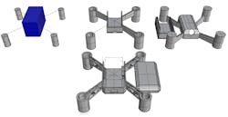
With the existing components represented in CAD, I could finally begin sketching new variations of the crash-resistant design. Putting the blind solids in CAD helped me explore the possibilities with a better understanding of the spatial relationships. I experimented with a variety of shapes and sizes and considered how each factor would contribute to an overall better design. Among other design decisions, I chose to change the arm structure to improve cable routing and add durability while creating a blockier, “kid friendly” hull—because nobody wants a drone that falls apart after its first flight.
Progress through different arm and body iterations.
Step 4: Isolate New Components and Iterate Individually
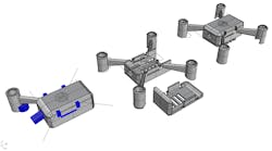
Working with a clamshell assembly, I took a shotgun approach and decided to try five different fixture schemes for the body of the drone. I was able to generate these small bodies fast using a 3D printer. Because I didn’t spend hundreds of dollars to print multiple designs, I could physically modify my design as much as I wanted before printing the final version.
The main challenge I found when creating the arms of the drone was cable routing. I tested a piping system for a cleaner look, but it added too much additional weight to be feasible. That led me to test trusses, which provided enough strength and simplified cable routing.
Scale study to consider larger drones.
Step 5: Prepare for Printing and Consider 3D Printing Constraints
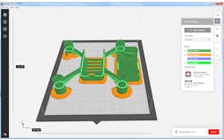
With a finished design mocked up in CAD, I imported the entire assembly straight from CAD into MakerBot Print to fine-tune print settings. I also viewed my design in an animated print preview to make sure every small detail would come out correctly.
Mass economy is important, so I dropped the number of shells to 1 and the infill percentage to 3%. Whether you’re creating a drone, a prosthetic, or anything else, you have to experiment with the shells-to-infill ratio to find the perfect balance. After a few tests, I finally figured out the perfect combination of shells and infill to keep the body light and the arms rigid enough to support the motor’s lift.
To ensure clean embossing on the low-relief logo on the top surface, I kept my text size larger than 8 point to avoid any spurring.
Preparing for 3D printing on a makerbot replicator mini+.
Step 6: Print, Test, Repeat
With the prints finished, I labeled everything before taking them off the build plate to begin assembly and weighing. This is the stage where I learned the most. Some parts didn’t fit perfectly, some arms were too heavy, and some component layouts that made sense on the screen were obvious failures in the real world.
So I took this batch of learnings and went back to iterating the individual components.
No print is sacred. I notated and broke iterations on the way to a final version.
Step 7: Fly the Printed Drone
After the final design changes were made, I sent the latest version to print. Then all that was left was putting the reengineered drone back together.
Reverse engineering the drone put my design and engineering skills to the test, while also allowing me to try out designs I would not have been able to experiment with otherwise. Getting to physically test those experiments allowed me to create, modify, and finalize the drone in real time without having to wait weeks, or even months, to see it.
The best part: I got to play a bit of forensics with why and how things are made. In this case, it was about discovering opportunities for improvement and learning more about the incremental improvements that define the iterative design process.

