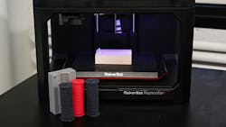
Having access to tools can greatly expand an engineer’s ability to build. As technology advances, it tends to become more accessible as it drops in price or increases user-friendliness. Once 3D printing was impossible to have in the home. Today, the technology has shrunk in size and cost to the point where having a 3D printer in the home is not only possible, but can offer a return on investment. As 3D printing becomes more accessible, people are finding more ways to use it.
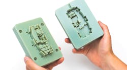
This article will walk through how to 3D print molds for silicone parts. 3D printing molds is not new, but it shows a different perspective on how 3D printing can help expand your building abilities. In the following examples taken from MakerBot, it took about 0.5 hours to make a silicone part from a 3D-printed mold, and 1.5 hours to make a silicone mold from a 3D-printed part. This time will vary, but it offers an idea to how fast 3D printing can offer a mold for prototyping or parts.
It is possible use flexible 3D-printing filaments, but they can be costly and might not match the hardness of silicone. Flexible filament will often be three times more expensive, require additional hardware, and print roughly 3.5 times slower than traditional filament. This doesn’t mean you need another tool to make silicone parts; rather, it’s a different way of using what you already have by printing a mold.
3D Printing Molds
This article will show how it is possible to use a 3D printer to make a mold; in Part 2, we will use a 3D-printed part to make the mold.
There are resources online to find designs of molds that have already been used to produce parts (Thingiverse, YouMagine, Cubify, MyMiniFactory, GrabCAD, Shapeways, Autodesk 123D, and many more). If you can’t find what you would like to make, you can use free online CAD software to design it.
When designing your own mold remember some basics.
- Draft angles – Straight walls inhibit part removal.
- Engraving and embossing – Make sure these features are pronounced enough in the molded part. Some resources suggest a minimum offset of 1 mm should be used.
- Post-processing – Remember that 3D-printed parts can have obvious lines from being built up in layers. A mold might require post-processing. This means tolerances and small features might need to be altered to accommodate for this. For more information on finishing 3D-printed parts, click here. Be aware of any post-processing on mating surfaces could affect how the mold fits together. This can increase problems such as flash.
- Parting line – If a part is not symmetrical, try to find the most effective place to split the mold.
- Limitations of 3D printing – Like any machining process, having fillets or chamfers on interior corners can be beneficial. For 3D printing, know your printer’s tolerance; don’t expect to have a corner that is a perfect 90 degrees. On an internal corner, if your printer is accurate to two microns, you will have a two-micro curve no matter what you do.
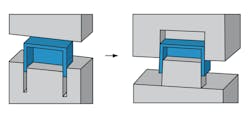
This image of deep ribs was taken from one of the many tips found on Protolabs’ website. (Credit: Protolabs)
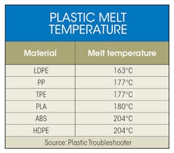
Also be aware of the materials you are going to cast with the mold. Different 3D-printing filaments have different melting points. If the material to be molded is a urethane, an exothermic reaction is possible. This added heat may degrade a mold faster than intended. 3D-printed parts have also been used to print injection molds. One early example was a 3D-printed mold that made over 600 spoons. The temperature of the material used in the mold can affect the molds endurance (see table).
Whether a design is downloaded or an original creation, it should take advantage of the 3D-printing process. Working complex geometries into a part can add value. While channels and sprues might seem like an obvious feature, remember you can print the part, or iteration number into the part.
After getting a CAD design that works well as a mold, and finding a suitable material, print the mold. From this point, it is more or less standard operating procedure. In the example from MakerBot, a 3D-printed mold is used to make a part out of silicone. This is a nice material to mold because it doesn’t require heat or generate heat that degrades the mold. In addition, removing soft material such as silicone from a mold is often easier, or requires less force, than ridged materials. Removing parts with less force can extend the mold lifecycle.
Remember Mold Release
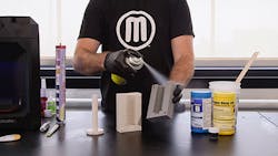
Mold release isn’t expensive, and unless you want to wax the entire surface, the spray will save you time in setup and frustration in removing the part. Once covered with mold release, clamp the mold together. It might also be a good idea to clamp, or secure, the mold to a surface if there is any concern that the mold might tip while pouring or setting.
This photo of mold release spray being used was taken from the MakerBot guide on how to print molds for silicone parts. (Credit: MakerBot)
Next, mix the materials. Unless you have a short cure time, take your time when mixing to prevent air bubbles. Another tip (that may just be a personal preference) is to try measuring using a scale rather than the lines on the measuring cup.
Once measured and mixed, make sure you check what time it is, or set a timer. This is so you can keep track of the time it will take for your part to set up. The amount of time a mixed viscosity takes to increase or solidify is measured from when it was mixed at room temperature (23°C)—this is often referred to as the “pot life.”
Carefully pour the mix into the mold. After the pot life time is met, carefully remove the part. Now remove any flash, or any other desired post-processing. You now have the basic knowledge to mold with a low-cost 3D printer. Let me know if you have 3D printed any molds, whether you’re an engineer or hobbyist. Tell me a little about your project and attach an image—we might use submissions for a future series.
