Download this article in PDF format.
Hydraulic pumps, cylinders, and other actuators deliver greater power in smaller packages than engines, electric motors, and mechanical actuators. Hydraulic valves easily control direction, speed, torque, and force with anything from simple manual operation to sophisticated electronic controls.
Yet, production methods that create these hydraulic components have not kept pace with the expanding scope of their applications. Enter metal 3D printing—it offers new opportunities to capitalize on the high power density of hydraulic technology by improving the design and production of components such as manifolds, valve blocks, and valve spools.
Three-dimensional printing, which began as rapid prototyping, has progressed beyond its original plastic materials to encompass many metal alloys. Although not practical or cost-effective for high-volume production, 3D printing offers many advantages when producing metal hydraulic components in smaller quantities and special designs.
Without the limitations of conventional machining, parts can be designed for the most efficient combination of production and performance. And internal channels can be optimized for higher flow and lower pressure drop. It’s also possible to produce several different prototypes within hours to determine the best design. Furthermore, components can be made from a variety of materials, including stainless steel (from AISI 304 to AISI 316L), aluminum, titanium, and new materials still under development. Sources of potential leakage from auxiliary drilling and subsequent plugging are eliminated.
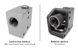
Although hydraulic components can be produced either by traditional manufacturing or 3D printing, traditional manufacturing is a subtractive process that starts with a larger piece of material, usually a metal casting or bar. Material is removed, generally by CNC machining, to leave the desired shape. Excess material often is left in place to save the expense of removing it, resulting in parts that weigh more than necessary.
Machining also is limited in its ability to produce many desired configurations. Passageways in conventional manifolds often must be positioned to prevent cross-drilled channels from intersecting and allow enough material between channels to provide adequate strength. Auxiliary holes drilled to connect internal passageways may need to be plugged, creating the potential for a future leak.
Three-dimensional printing, by contrast, is a form of additive manufacturing, which builds up the desired part layer by layer. With 3D printing, flow channels can be placed exactly where they are needed, and in optimum size and shape. Until now, flow channels, particularly in components such as valve spools, generally have been circular because they are machined with rotating cutters. By building a component in layers, designers can specify configurations that would be difficult or impossible using conventional manufacturing methods.
For example, flow paths can be made with cross-sections that are square instead of round, increasing flow capacity by 20% with the same channel width. Channel design can be optimized to achieve greater flow within a smaller space. Passageways connecting internal channels don’t have to be machined from outside a manifold, eliminating the need for hole plugs.
The process uses a computer-controlled laser to melt each layer of metal as it is deposited to build up the part. According to Alberto Tacconelli, Managing Director at Aidro SrL, Taino, Italy, the most appropriate type of metal 3D printing for hydraulic components, at the moment, is powder bed fusion, either by direct metal laser sintering (DMLS) or selective laser melting (SLM).
DMLS heats the metal powder to the point that particles fuse together on a molecular level. The porosity of the sintered material is controllable. And DMLS can be used with a variety of alloys, allowing functional prototypes to be made out of the same material as production components. With SLM, the metal powder is not merely fused together, but is actually melted into a homogenous part by a high-power-density laser. Because of reduced porosity, parts made with SLM can be stronger, with greater control over crystal structure. However, the process is said to be feasible only when using a single metal powder.
When is Metal 3D Printing Appropriate?
Tacconelli cites these points to consider when deciding whether or not to produce a part using 3D printing:
Quantity—Traditional manufacturing is more suitable for large-scale production, whereas 3D printing may be more economical or practical for small volumes of complex or specialized hydraulic components.
Production lead time—Subtractive processes, such as CNC machining, may require lead times of 30 to 60 days to produce a component from metal bar stock, or as long as six to 12 months if a casting is needed. For 3D printing, hydraulic components can be printed on demand in a matter of days. If the printed parts require tooling, lead time may increase up to one or two weeks.
Prototyping—With 3D printing, several different variations of a prototype can be produced at the same time, making it possible to evaluate design alternatives.
Material selection—Hydraulic components must have adequate strength and corrosion resistance to safely handle the high pressures typically found in hydraulic systems. Three-dimensional printing can offer a broader selection of materials, including stainless steel (AISI316L), aluminum, titanium (Ti6Al4V), Inconel (625 or 718), and maraging steels.
What About Material Properties?
Because metal 3D printing is relatively new to the field of hydraulics, it raises the question of how the material properties of 3D-printed parts compare to those made by traditional processes. Although typical mechanical properties such as tensile strength, yield strength, and modulus of elasticity appear to be comparable, depending on material choice, the high pressures often encountered in hydraulic systems merit additional consideration.
With proper material choice and design, components can be made to withstand these pressures, but they also may encounter shock and pressure pulsations, which are more difficult to accommodate. Manifolds, for example, often have been made from ductile iron or other ductile materials to handle these pulsations, but these materials do not lend themselves to the additive-manufacturing process. Iron and carbon steel materials also fall into that category, because the source material must exist in powder form.
Tacconelli says that, while not all metals can be 3D-printed, Aidro normally uses aluminum and stainless steel to 3D-print hydraulic manifolds. He states that the mechanical proprieties of these materials are equivalent to (or in some cases better than) metals produced from bar stock. The results, he adds, are as much the result of design as material.
The company uses the finite element method (FEM) to predict how a product will react to real-world forces and show whether it will work the way it was designed. Tacconelli explains that “with good design methods, we can 3D-print a hydraulic manifold that can withstand pressure peaks in the system without any problems. We can increase the wall thickness and change the shapes of the channels where the FEM analysis indicates a potential failure.” After printing a manifold, the company tests it in-house and performs further tests with the support of Polytechnic University of Milan.
The specific metal 3D-printing process and the equipment choice also affect the results. Tacconelli says, “After careful evaluation, we have chosen the direct metal laser sintering process that, in the case of hydraulic products, guarantees better accuracy and produces a smoother surface finish.” He adds that certified machine parameters and high-quality metal powder guarantee the repeatability of the process and quality of the products.
A combination of factors can affect the properties of a finished part and be used to control the final outcome. Tim Simpson is a professor of mechanical and industrial engineering at Penn State University, and co-director of the Center for Innovative Materials Processing Through Direct Digital Deposition. He says that each object will heat and cool a bit differently, depending on the speed and energy as it interacts with the metal powder. This “thermal history” will then affect the object’s microstructure, which, in turn, affects its material properties, such as strength, stiffness, and elasticity.
Simpson, who also was the 2015 chair of ASME’s Additive Manufacturing and 3D Printing Conference and Expo, points out that most 3D-printed metal objects require some post-processing heat treatment because of the stresses that build up from the repeated heating and cooling caused by the laser. He explains, “For traditional subtractive processes, you start with a known material and then create the shape. But in this case, you 3D-print a part to create the shape, and then you heat-treat or solution-anneal it to actually get the material you want.”
Progress also is being made to 3D-print some alloys that previously were not suitable for additive manufacturing, including high-strength unweldable aluminum alloys such as Al 7075 or Al6061. These alloys normally develop severe hot-cracking, which could occur with laser heating the 3D-printing process. To solve that problem, HRK Laboratories LLC developed a technique that combines these metal powders with nanoparticles, which prevents the hot-cracking and results in a printed part with full-alloy strength.
As stated, 3D printing is best suited to smaller volumes. But its ability to reduce part weight by using optimum amounts of metal makes the process ideal for applications that require high precision and light weight, such as aerospace, aviation, and medical equipment. Agricultural machinery is another important area, where this technology can be used for prototype parts, tooling and spare parts, as well as specialized low-volume production parts. In general, 3D parts are also best suited those that must be more compact than can be achieved with conventional manufacturing techniques.
Typical Applications
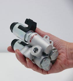
Many types of hydraulic components already are being produced with 3D metal printing. For example, Aidro printed a hydraulic valve block in stainless steel to control a single-acting cylinder (Fig. 1). The company was able to save space and optimize its internal channels for higher flow with lower pressure loss than with conventional components. Because auxiliary drilling was not required, the potential for external leakage also was eliminated.
1. 3D-printing this hydraulic valve block in stainless steel reduced its size and improved flow. (Courtesy of Aidro SrL)
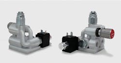
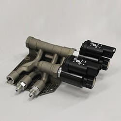
In addition, the design and production of a stackable hydraulic valve was improved with 3D printing (Fig. 2). The direct-operated pressure-reducing valve had been made of steel and zinc-plated to resist corrosion. When Aidro’s customer needed a small quantity of the valves, the lead time and cost of CNC machining were not acceptable. Instead, the valve was redesigned for 3D printing in stainless steel, which reduced the weight by 60%. Its structural walls were as strong as in the original part, and the new design was tested under pressure to 250 bar with comparable results.
2. The hydraulic valve on the left was machined from steel, and then zinc plated for corrosion resistance. The redesigned valve (right) was produced by 3D printing in stainless steel. The 3D-printed version weighs 60% less but maintains the same strength as the machined part. The conventional part could have been made lighter by machining away (subtracting) unneeded material, but with much higher production costs. (Courtesy of Aidro SrL)
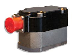
For several years, Domin Fluid Power, Bristol, England, has been developing hydraulic valves, pumps, and more complex subsystems designed specifically for metal additive-manufacturing production. The company will be launching a direct-drive hydraulic servovalve with on-board electronics (Fig. 3) as its lead product in the first half of this year.
3. Expected to be introduced later this year, this direct-drive servovalve with onboard electronics promises substantial advantages over current designs at a competitive price. (Courtesy of Domin Fluid Power Ltd.)
Marcus Pont, General Manager at Domin, says the new servovalve offers improvements over current designs in rated flow for size, efficiency, and weight while maintaining a competitive price from simplified manufacturing. These performance improvements are based on comparisons with current state-of-the-art servovalves.
Compared to a significant competitive product, Pont says the Domin servovalve provides a 25% rated flow improvement for its size, with 20% less leakage. It also takes up 25% less volume, 15% of the weight, and contains 40% fewer parts, which simplifies manufacturing.
4. This 3D-printed manifold for agricultural machinery is half the size and weighs 75% less than a conventionally manufactured part. (Courtesy of Aidro SrL)
Another example from Aidro is a hydraulic manifold used in agricultural machinery (Fig. 4). This manifold controls a double-acting cylinder with two solenoid valves and two pilot-operated check valves. The 3D-printed manifold performs exactly the same functions as the unit it replaces, but is half the size and 75 % lighter than the previous manifold. The part consists of AlSi10Mg, a 6000-series aluminum alloy that combines good strength and thermal properties with low weight and flexible post-processing potential. It is often is used for parts with thin walls and complex geometries.
Aidro’s Tacconelli reports that pressure tests have shown mechanical properties—such as tensile strength, elongation, impact toughness, and hardness—to be as good or better than a manifold made of traditional materials. Operating performance is comparable to or exceeds the traditional part because the curved shapes of the internal channels have no 90-deg. angles at intersections.
5. This hydraulic manifold, 3D-printed as a single piece, weighs 70% less than the 17-piece assembly it replaced, yet it withstood the same pressure and fatigue testing. (Courtesy of Penn State CIMP-3D)
At Penn State’s CIMP-3D, a hydraulic manifold was 3D-printed as a single piece (Fig. 5). It weighs 70% less than the 17-piece assembly it replaced, yet withstood the same pressure and fatigue testing.
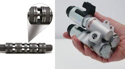
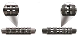
Aidro redesigned a valve spool to be 3D-printed with new hole forms, replacing round holes with square holes (Fig. 6). This increases the area of the oil passage inside the spool and reduces pressure drop.
6. The original valve spool (left) had round holes, required with CNC machining. The spool redesigned for 3D printing has square holes with larger area to reduce pressure drop. (Courtesy of Aidro SrL)
These are just some of the ways metal 3D printing is expanding the potential for improved component design and production in the hydraulics field. According to a report by Infinium Global Research, the global metal 3D-printing market is expected to experience a compound annual growth rate of 33% for the years 2017-2023. Hydraulic applications promise to be a significant part of this expanding field.
