Aerospace Opportunities Demand Quick Resolution to 3D-Printing Issues
Download the PDF of this article.
If you fly in a plane in the next few years, you are statistically likely to be flying in one that contains 3D-printed parts, also known as parts made via additive manufacturing (AM). While Stratasys says 3D printing is great for interior parts, Airbus announced plans to 3D-print 30 tons of metal parts every month by 2018. Some of them will be the brackets and structural parts that hold the plane together. In fact, aerospace manufacturers are working 3D-printed parts into just about every facet of the plane, including engine parts.
General Electric (GE), for example, is planning to mass-produce 25,000 LEAP engine nozzles with 3D printing. According to a ReportsnReports study, “The Global Aerospace 3D Printing Market to Grow at 55.85% CAGR during the period 2016–2020,” the primary driver of 3D printing in the aerospace market is the miniaturization of jet engines. The more widely additive manufacturing is used, however, the more issues come to light—ranging from the price of powders and resins to potential supply-chain weaknesses. Yet the aerospace industry has so fully embraced 3D printing that it will undoubtedly support the resolution of such problems.
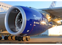
The Trent XWB engine is also used on the Airbus A350 XWB, which made headlines with its use of 1,000 3D-printed parts that helped the company stay on deadline.
The reason behind the big push for additive manufacturing is simple: savings. Reducing the size of parts and being able to print multiple parts in one print sounds like low hanging fruit, but according to Airbus, using 3D printing could reduce the weight of a plane by more than a ton. Virgin Atlantic and American Airlines have been quoted as saying that reducing a single pound across a fleet could save 14,000 gallons of fuel per year.
These numbers might fool some into thinking that 3D printing is an easy and obvious choice. However, switching to 3D printing has challenges. “Component costs are too high when compared with established manufacturing technology—for example, casting and forging,” says Professor Moataz Attallah, director of the Advanced Material and Processing Lab at the University of Birmingham (UK). “Deposition rates of processes are too slow, making a weak business case in depreciation vs. build rates.” In addition, the process isn’t as autonomous as people might think. Parts could need more labor in post processing than in printing it. Attallah makes the following points:
- Powders and resins can be expensive for mass production—and in the case of metals, not tailored/designed to AM (80% of research focuses on Ti-64, IN718, & AlSiMg Alloys). As a result, powder can be difficult to obtain.
- Product quality is inconsistent between batches and/or machines. The insufficient or changing data makes it difficult to construct accurate business models.
- Lack of in-line monitoring/control.
- Post-processing (e.g., hot isostatic pressing, surface finishing, or machining) is always required.
Although not everyone agrees with this, Karl Hranka of 3D Hybrid Solutions says, “The laser deposition process produces rates over 20 pounds per hour, for parts over 1000m3 which easily justifies the cost of the metal AM tool.”
There are companies working on these concerns, these issues show that companies have to weigh the risks and opportunities in AM research. The decision can be one of the following:
- Do nothing; wait and see.
Positive: Investment in metal AM involves a high risk.
Negative: The risk of missing an opportunity.
- Develop an individual long-term strategy.
Positive: Protect any potential IP, develop a strategy that matches the company’s products.
Negative: Resources and cost.
- Develop a strategy involving academic & industrial supply chain partners.
Positive: Sharing the cost, effort, knowledge, and resources.
Negative: The risk of not securing the IP.
There are inherently pros and cons to everything. However, the companies that solve the concerns cited by Professor Attallah will continue to grow 3D printing in the aerospace industry. The benefits seen by 3D printing have been so great that a company able to execute a plan with this process might get a leg up on the competition. The following outlines some of the concerns for using 3D printing for the aerospace industry, and how some companies addressing those concerns.
Supply Chain
Acquiring companies to secure a supply chain is not a new concept. Collaboration and/or mergers to control the powder metals might indicate which company will excel with 3D printing in the aerospace market. If 3D printing continues to be an asset in this market, whoever corners the supply chain could possibly lead the market.
Controlling supply isn’t the only challenge, however. It is also necessary to innovate. It is only through experience of these processes and designs that companies, such as Rolls-Royce, were able to set a record for the biggest part ever 3D printed. Using electrobeam or additive laser manufacturing (ALM), Rolls-Royce was able to generate this part. “There are two real benefits to ALM,” says Simon Burr, director of engineering and technology for civil aerospace at Rolls-Royce. “The lead time in engine development is dramatically reduced and the design freedom it offers as opposed to conventional casting or machining; both could be significant.”
The Trent XWB engine is also used on the Airbus A350 XWB, which made headlines with its use of 1,000 3D-printed parts that helped the company stay on deadline. In another example, the Airbus A310 line required about 100 plastic safety belt holders per year. However, this was a 30-year-old design, the company had gone out of business, and the molds were lost. Engineers redesigned the part in about two hours and delivered a finish product a week later using 3D printing.
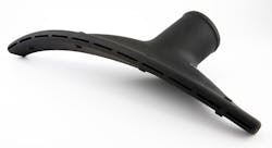
This 3D printed part for Bell Helicopter improves overall airflow, offers built in supports, and has the part number printed directly on it. This would not be possible with the rotomolding process.
Generating new molds could have taken more time and cost thousands of dollars. But tooling isn’t the only benefit driving 3D printing in the aerospace industry. “One of the applications for Stratasys Direct Manufacturing was for environmental control system ducting. This is the HVAC to keep everyone in the aircraft comfortable,” says Chuck Alexander, director of product management at Stratasys Direct Manufacturing. “The aircraft and aerospace companies were looking for a more efficient process to make these parts. Previously, they used rotomolding. By using AM, they gained significant cost savings by reducing the amount of parts and tooling. And they are able to include extra features that weren’t possible with rotomolding, such as the brackets and diverting vanes.”
In addition, many interior parts have flame, smoke, and toxicity requirements (FAA 25.856) to allow passengers time to get out of the aircraft in case of a fire. Such regulations guide material selection for the interior of aircrafts.
Product Quality
Just a couple years ago, powder, and powder quality were points of concern. Yet 3D printing has grown so much that companies began planning for this demand. It doesn’t take long until someone figures out an effective supply.
LPW Technology views metal 3D printing from the perspective of the powder. Powder metallurgy started by essentially grinding scrap metals. LPW founder Dr. Phil Carroll says, “Garbage in, garbage out. It’s more than just supplying powder. You have to understand how the shape, size, chemistry, and flow of the powder affects the finished product. You can’t use the same model as some plastic 3D printers, which is if you buy their machine, you have to buy their material, especially in the aerospace sector, where there is the need for traceability, documentation and certifications.”
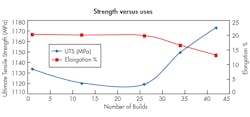
In traditional processes, the materials are used once, so a provider will certify the metal feedstock one time. The interesting thing with 3D printing is that it’s possible to reuse the powder. But recycling powder does change the properties of the metal powder, and in turn, those of the resulting part. Over time, unsintered reused powder will typically show signs of degradation, leading to changes in the mechanical properties and reliability of the end part.
Effects of number of builds on mechanical properties of Inconel 718 tensile specimen produced byPowder Bed Fusion. The properties would indicate the material is becoming less ductile, which can make it difficult to determine when the material would fail. (LPW Case study: Vacuum vs non-vacuum melted gas atomized powders)
Understanding this degradation is necessary to know how often a powder can be reused before needing to be recertified, used in a non-critical application, or thrown out. As 3D printing grows, research is providing data on the effects of the material degradation, which is important in high-quality industries. Contamination in powder metals could cause a part to fail. Furthermore, as 3D printing redesigns parts to reduce material, having every particle of powder perform within its published properties becomes increasingly important.
“The industry calls contamination a High Density Inclusion, or HDI,” says Carroll. “At LPW we refer to it as ‘the devil particle.’ One of the common ways a powder becomes contaminated is during processing. Not only is handling the materials important, but as you reuse metal powders oxygen levels potentially increase in the material; effectively contaminating itself. Some powders pick up oxygen more quickly, and other contaminants can fall into the powder; for example, dust, skin, hair, etc.”
In January of this year, Lloyd’s Register—a research, education, and safety company—and TWI, a manufacturing and engineering firm, launched a new project to advance the adoption of AM. While LPW is certifying the powder, LR and TWI are starting a project to certify laser powder AM components. All of this will propel 3D printing, but testing and inspections take time and money.
Lack of In-Line Monitoring/Control
New ways to test without stopping production are being created. Research is able to provide enough data to create a process window. By comparing real-time data to test data, it is then possible to determine the finished properties of a 3D part. The key is that this data can be collected without stopping or interfering with production.
One example is Sigma Labs, a software company that is helping to assure the quality of metal AM parts. The company started with some related work when Boeing was developing its 787 Dreamliner. Boeing was looking for quality assurance software to effectively get rid of the inspector. “Having a digital thread that follows a design from concept to finish gives the regulating bodies (in aerospace, it’s the FAA) objective evidence of compliance,” says Mark Cola, CEO of Sigma Labs. “Quality assurance software can track a process and part and verify that as long as everything documented in the digital thread was within a specific window, or parameter, that part can be certified.”
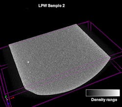
Here is the output from a CT scan of titanium alloy powder. The sample is relatively small, but contains over 100,000 individual particles. The white spot in the left of the image shows an inclusion. This may be a small spot, but even a small contamination can start crack propagation, and lead to failure.
This is only able to be done through the understanding of the entire process: thermal history, microstructure, mechanical properties affecting end-product performance. This means a lot of trial and error in the laboratories during process window development. This creates the process window for production to follow. Measurements during development increase the accuracy of quality software for use in production. To obtain data without interfering with production, Sigma Labs uses non-contact thermal sensors to track the melt (weld) pool and the part temperatures during the print. This data, with previously tested research, helps verify the properties of the finished product without a separate inspection step.
In-line verification may need to process a lot of data. Furthermore, processing data locally can increase real-time performance by eliminating any lag and cost that might happen from a massive amount of data constantly being uploaded and downloaded to a Cloud-based server for analysis. Products increasingly contain Systems on a Chip (SoCs) and/or Field-Programmable Gate Arrays (FPGA) to enable information processes to be handled locally allowing for Edge Intelligence to only send necessary data to IoT servers for later gathering of additional manufacturing intelligence.
For example, the Modular Industry Computing Architecture (MICA) released last year by Harting is an open hardware and software system that temporarily saves, evaluates, and processes data close to the machine or at the edge of the Industrial Internet of Things (IIoT). Sigma uses Edge computing devices to locally process the mass of data from the photo-thermal sensors to verify that the weld pool and part are operating within the processing window. SoC, FGPA, and products like the MICA will become more important as more manufacturers move to an in-line inspection or expand the IIoT.
Post-Processing
Retrofitting is also expanding the use of 3D printing of aerospace metals. Finishing a 3D-printed part can be more expensive than printing it. Some printer companies are using the same technology and G-code used to print a part to also finish it. Printers have started including CNC machines with the printers. However, this would not work with a powder-bed process; the powder would be in the way. CNC machines can work for laser deposition or powder jetting processes. Called hybrid printing, the process helps generate required surface areas, tolerances, and geometries. This is imperative in the aerospace industry, especially for jointed or welding surfaces in assemblies.
One tip for printing metals quicker is to oversize the print by as little as 1%, then finish the print with a CNC machine. This lets the part have the same tolerances and surface finishes as a part generated completely by the CNC machine. In addition, this technique lets the printer put down as much material as it can, as fast as it can, without too much concern for tolerance. The deposition rates vary, but these techniques can layer around 5 to 20 lb. of material per hour.
“You can save a step and just retrofit a deposition print head to a 5-axis CNC machine,” says 3D Hybrid Solutions’ Hranka. “Turning CNC machines into hybrid—additive and subtractive machines—has several inherent benefits. You don’t have to buy another machine. The build space is the same as your CNC machine. You don’t have to load and unload parts from one machine to another. Also, if you attach this to a 5-axis machine, you can print features on various axes. Finally, a part can be CNC machined during the print.” Having the ability to switch to and from subtractive to additive means you have the ability to obtain tolerances on interior features before they are encapsulated. This could have great applications in the aerospace market.
Ultimately, 3D printing is changing the aerospace industry. The process results in lighter parts with shorter lead times, fewer materials used during production, and a significant reduction in the manufacturing process’ environmental footprint. “We are on the cusp of a step-change in weight reduction and efficiency—producing aircraft parts which weigh 30 to 55% less, while reducing raw material used by 90%,” says Peter Sander of Emerging Technologies and Concepts at Airbus. “This game-changing technology also decreases total energy used in production by up to 90 percent compared to traditional methods.” As challenges are increasingly overcome, additive manufacturing promises to bring enhanced benefits to the aerospace industry.
