Get the Most Out of Your FDM 3D Printer, Part 2
This file type includes high-resolution graphics and schematics when applicable.
In Part 1, I detailed some ways to expand the usefulness of your FDM 3D printer. In this installment, we will look at some other ways to leverage this device in the growing field of additive manufacturing.
Thermoset Parts
Another usage for 3D printers involves making negative or positive molds for thermoset or even thermoplastic parts. The 3D-printing molds for prototypes can lead to the material’s properties being closer to the production part than is possible when 3D printing the part directly. The accuracy of 3D molds is good enough to produce threaded inserts and two-part molds.
Creation of thermoset parts, using materials such as epoxy and urethanes, is pretty straightforward. You print a negative of your part, pour in the liquid, and wait for it to set. The end result is a finished part. Think of Jello molding.
Be sure to utilize as much draft as possible for rigid parts. Use a mold release spray in your cavities and don't forget to scale your molds to account for material shrinkage—if your application requires that level of accuracy.
Vacuum degassing, i.e. getting rid of the bubbles in your material, is recommended for any material that you had to mix vigorously prior to pouring. It’s easily done for small parts with a shop vac and a sturdy enclosure that will fit around your mold. This video shows an example of a DIY system:
The air bubbles expand while under the vacuum and will eventually exit the material, causing it to collapse again. This means you want to make sure the container for the material has ample room to expand into; otherwise, it will overflow inside the vacuum chamber.
Thermoplastic Parts
Thermoplastic parts are a bit more involved with an FDM printer. For this, you print a “scaled for shrinkage” positive of your final part. Keep in mind that the simple method presented here is really only practical for parts with a straight mold split line.
Make an epoxy negative casting of each half of the part. Put the two halves together and use a plastic injection machine like those offered by www.techkits.com. This site offers a pretty complete tutorial on the whole process, not to mention the equipment. We are just starting to experiment with directly printed mold halves using Objet printers from a contract printer, which eliminates the epoxy molding step.
Whether printing a mold or a finished part, orientation for circular and curved features parallel to the XY plane for best definition will be important. If your machine uses a separate support material, another nuance to be mindful of is how to orient the part to minimize usage of support material. This, of course, saves material and time during the build, but will also save time and frustration from removing supports after the build. It may even eliminate the need to soak the part in the dreaded NaOH bath for soluble support material.
Free software from Cideas (at https://truequote.buildparts.com) shows how build orientation affects the cost of a part. There’s also a list of tutorials on YouTube.
Support Material
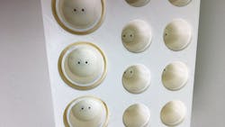
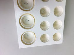
All FDM printers can print surfaces without supports or support material that go beyond vertical (i.e., overhanging), but only up to about 45 degrees. Your printer software will likely show you, during the generation of the printer files, if support material is needed. Or you can simply run an experimental build with various angles and see when support material is needed.
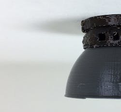
Try printing a half sphere and see where the support structure stops (see the second image above). This is not important if the design has some flexibility. However, it can be possible to save time and money by tailoring the design to the printer’s strengths and be able to use a part right out off of the build platen. Instant gratification is one of the best parts of 3D printing, right?
Many times some support material is inevitable. Does that mandate the part going into the bath? Definitely not. Manual removal of support material is possible without harming the model. A good set of mechanics picks and a sturdy putty knife will be your best tools for this task. And wear safety glasses when removing the support material—the support material is extremely brittle and sharp, and shards can pop off the part with pretty good speed.
Still can’t get all of the support material out? Sometimes we leave the remaining support material in place if it's on a non-visible surface or feature inside the part. Or maybe it’s an end-use part for manufacturing, where aesthetics aren’t important. Of course, sometimes one is just resigned to soaking. This is often the case with small or intricate parts, or when it’s just not possible to remove the support material mechanically.
To minimize time in the bath, remove as much material as possible by hand and make sure the bath is warm ahead of time. After removal from the bath and a thorough rinsing, we often bake the part dry in the heated environment of the printer if we’re in a hurry.
Warping
A well-known problem with the FDM process is that of warping of relatively thin, flat parts. A lot of thermal expansion and contraction occurs during the process of laying down layers of molten plastic, and warping can occur where the outer edges of the part warp up in the Z direction. At best, you get some smearing and roughening of the part; worst case is a print-head crash. Some printers even have a low-density print mode to help with this issue. Unfortunately, it’s usually not enough, and you don't find out until well into the print job.
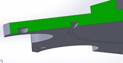
Part of the issue is that the support material adheres to the build platen better than it does to the model material. To take advantage of this fact and print flat parts, we add female dovetail features to the bottom of the part, which essentially lock the model material to the platen.
Some days I feel like a lazy engineer. The process to get a part made used to be: Design the part, make a manufacturing drawing of it, get it checked, send out for three quotes by faxing the drawing, wait for quotes to come back, pick a vendor, issue a purchase order, wait for the part, inspect the part, and then, finally, put it to use.
Now, though, I can have a finished part in a couple of hours—from a CAD model to the printer. Of course, the reality is this will be the norm in a few short years for parts in a variety of materials. Remember how amazing it was that you could send an actual copy of a sketch, drawing, or letter over the phone lines (that is a "fax" for those of you who don't recall!)?
About the Author
JB Babcock
Director of Engineering
JB Babcock is director of engineering at Taylor Technologies (www.taylortechnologies.com) and is also an engineering consultant and an expert witness. He has over 30 years of experience in machine design, factory automation, and consumer product design. Prior to joining Taylor Technologies, Babcock was director of engineering at Sun Automation group, and before that ran his own engineering consulting firm for 14 years. JB earned a master’s of engineering management from George Washington University and B.S. in Mechanical Engineering from Lehigh University.


