Q&A: Design for Electrification, Design for Ergonomics and New Analysis Tools
CAD design software is a key tool in the design engineer’s arsenal for accelerating product design. The best tools are those that support complex design and foster innovation through advanced technologies. Generative design and real-time simulation are fast becoming standard features.
For this interview, contributor Robert Farrell spoke to PTC vice president of product management, Paul Sagar, about Creo 10 and Creo 10+. The latest release in PTC’s software suite has expanded features, including generative design, additive manufacturing and advanced simulation capabilities. And it all leads to a digital thread with transparency across the entire product lifecycle.
Robert Farrell: Thank you for your time today, Paul. Let’s start with the big picture. Can you provide us with an overview of the PTC Creo suite and a little about what’s new?
Paul Sagar: Creo is a comprehensive 3D CAD solution that helps companies accelerate product innovation, build a competitive advantage and gain market share. We combine powerful, proven functionality with new technologies such as generative design, augmented reality, real-time simulation, additive manufacturing and the Internet of Things (IoT) to iterate faster, explore more design concepts, reduce costs and improve product quality.
Each release emphasizes a theme designed to advance usability and productivity. In Creo 9, simulation-driven design and design for manufacturing were our primary initiatives. We introduced tools for managing, manipulating and understanding CAD models along with enhanced tools for ergonomics, Model-Based Definition, simulation, generative design and additive manufacturing.
Our latest release continues our commitment to empowering designers in the evolving world of product design. Creo 10 themes include design for electrification and design for ergonomics along with new analysis tools.
RF: Design for ergonomics…Can you talk about that?
PS: Many PTC customers build products operated by humans. Because a growing number of these products require human interaction, we’re expanding our capability around ergonomic design, including visual field.
Ergonomic design uses a digital mannequin to represent the human perspective and provide an understanding of how a human will interact with a given environment. We did a lot of work to improve the general usability for mannequin positioning. For example, one can now determine if the passenger can easily reach a handle in your product or something similar. Going forward, this is an important aspect of design and we will continue to expand and enhance this.
RF: You mentioned visual field. Can you elaborate?
PS: Visual field allows users to ensure that designs meet certain safety standards. With this tool, users can create geometry or generate a cone of view with sightlines accounting for limitations and obstructions. For example, if I look through a windshield my field of vision is obstructed somewhat by the pillars of the vehicle or a lowered sun visor. In Creo 10 we expanded this to now include reflection analysis as well. I can look at the side mirror and Creo will generate a cone capturing my field of vision. This feature includes controls to manipulate the mirror’s angle. Again, it’s all about understanding design from the operator’s perspective.
RF: Let’s talk about electrification. This area is gaining a lot of momentum these days.
PS: As the world moves in this direction, there’s a growing drive for improving electrification design. In Creo, we have a full set of capabilities to design schematics for wiring harness, lay out all your wiring harness inside the 3D model and then take it to manufacturing.
For Creo 10 our focus is to make it easier to understand in the 3D environment. Expanding our cabling tools provides a better understanding of cable routing, what cables you have, their connectivity, setup of the bundles, and the ability to split and merge harnesses.
RF: Can you give an example of this?
PS: Because of the increasing complexity of harnesses, we’re finding that customers are building a harness and then saying, there’s a section of the harness that could be a self-contained subsystem. What I might really want is to extract that sub-system so it can be reused in a different design.
We provide the ability to split out that portion of the harness, create a subsystem and take all the logical information with it. Maintaining all the references and connectors will allow you to place it in a new harness and improve efficiency by reusing an existing design.
RF: You mentioned simulation as a key Creo 10 component. What types of simulation does Creo support?
PS: Creo contains a broad set of simulation capabilities. We’ve continued to expand Creo Simulation Live, our real-time simulation solution powered by Ansys. Now it’s easier to establish contacts between multiple components within a design. This supports structural simulation, modal simulation, thermal, as well as fluid simulation—all in real time.
RF: What about capabilities outside of Creo Simulation Live?
PS: One of the most noticeable changes in Creo 10 is the introduction of a new composite design environment. Composite materials are no longer found only in aerospace or motorsport. Whether you are in wind energy, automotive, industrial equipment, yacht design or many other industries there is a growing move towards using composite materials. The ability to add strength, stiffness, impact absorption at exact locations, making highly optimized and light components, is making this process more attractive to many industries.
READ MORE: Outsourcing CAD Engineering Delivers Savings, Flexibility
As such we have introduced a new set of capabilities to enable users to design, simulate and manufacture their composite products. Starting with the ability to define the ply layup, add transitions between plies, add core material and even create the resulting solid geometry with accurate mass properties at the end. The draping of the individual plies can also be simulated to reduce shearing of the fabric.
We have expanded our Ansys partnership by introducing more advanced physics capabilities with our Creo Ansys Simulation Advanced package. Starting with non-linear contact, commonly referred to as sliding contact, enabling the simulation of use cases such as snap fits. With or without friction this provides the highly accurate answers you would expect from Ansys.
We also introduced support for nonlinear materials, most notably support for rubber deformation and behavior with the Neo-Hookean material model and bi-linear plasticity for true plastic deformation cases.
RF: Multiphysics and generative design are growing areas of interest. Anything new here?
PS: Yes, we’re continuing to expand both areas. It’s now possible to support Multiphysics allowing users to combine both thermal and structural physics to understand, for example, a thermal expansion use-case scenario.
Generative design is also heavily influenced by simulation. This allows an engineer to specify variables such as working conditions, loads, constraints, manufacturing criteria, material and so on. The system will then construct and generate the optimal shape. It’s an optimization engine that employs simulation behind the scenes to create, simulate, optimize, refine and iterate a design.
RF: You mentioned collaboration among software providers. Can you talk about PTC’s approach here?
PS: Partnerships are very important to our company and Creo as a product. We have some extremely smart developers, but maybe those resources aren’t experts in a particular vertical area. And so, in such instances, we tap the expertise of our partners.
For example, Creo has the capability to simulate the injection molding process. I’ve designed the part and I’m going to put this on a machine and inject it with plastic. Am I going to get weld lines? Will I get sync marks? How long is the filling process? We at PTC aren’t experts in that type of physics, so we partner with somebody who is. It’s all about delivering the best product to the customer.
RF: And these integrations are transparent to the user?
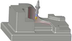
PS: That’s the key. We provide the functionality within the Creo environment. It looks and feels like any other Creo capability, but just happens to be using a separate engine. I mentioned Ansys for simulation and a different partner for injection molding. High-speed machining is another example where you’ve got specific algorithms and tool paths that are calculated to optimize the speed of the tool and optimize the cutting behavior. So, for machining, we leverage third-party experts who specialize in generating optimal toolpaths.
As a result, end-users get the functionality, support and continued enhancement that they’ve come to expect.
RF: Earlier you mentioned additive manufacturing. Let’s circle back to that.
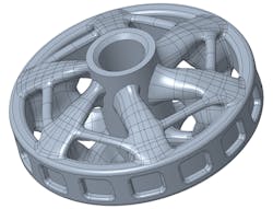
PS: While there are many solutions for additive manufacturing, the problem is they’re all point solutions that result in a broken tool chain. The key is to have a seamless process. At PTC, we’ve been working extensively on additive manufacturing.
Today, we have a vision to ensure that users can do everything they need to do from design optimization, analysis, checking and printing without leaving the Creo environment. Whether you’re designing an injection molded part, a machined part, a cast part, an additive manufactured part…it shouldn't matter. You should just be leveraging the same single solution to solve those problems.
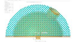
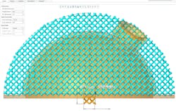
We’ve got a broad spectrum of tools to build, optimize and simulate complex lattice structures, to validate that those structures can be printed and place those parts on a print tray, and we understand the machine they’re going to be printed on. We understand the size, parameters and drivers of that printer.
With Creo 10, we’ve continued to add additional lattice cell types specifically targeted at the medical industry. These approved lattice cell geometries help bone to grow and attach to the additive part.
RF: What are auxetic cells and does Creo support this?
PS: Yes, this is an area of focus for us. Due to their cell shape Auxetic lattices possess a Poisson’s ratio. This unique characteristic allows structures to become fatter when stretched or thinner when squashed. This is important for companies that design products for energy absorption such as crash helmets. The engineer must know that the helmet will absorb the energy of the impact and auxetic lattice geometry will help significantly in solving that problem.
RF: The industry is changing quite a bit. What do you see as some of its emerging challenges?
PS: The answer to that depends on the vertical you’re in, the area you’re in or the business you’re in. One obvious challenge is to move analysis further upstream to the design stage. Historically, simulation has been thought of as an after-the-fact step: I design the product and then toss it over the fence to analysis. There is a need for analysis insight earlier because you’re trying to optimize and accelerate the design process. You’re trying to improve product quality. You’re trying to be more innovative. However, a lot of design engineers don’t feel fully comfortable performing simulations. It can be a complex task. They typically want to rely on a CAE expert.
Our Simulation-Led Design capabilities address this need by incorporating simulation capabilities into the design environment. Our challenge is to continue to advance this capability and arm designers with rich simulation capabilities in a way that is easy-to-use, intuitive and provides the insight to guide early design decisions.
RF: What tangible benefits are associated with simulation-led design?
PS: The benefits are measurable across the organization. We’re talking about faster development time at lower costs and the ability to boost innovation by exploring more design alternatives. It’s also very important to mention that this also frees analysis resources to focus their expertise on more complex or high-profile simulations. It’s all adding value to design and analysis resources.
RF: Any other challenges?
PS: I'll call it digital thread, but at a lower level, it’s probably moving into model-based enterprise where more and more companies out there are looking to get rid of 2D drawings. Drawings are open to interpretation. I can give a drawing to five different people, and they will interpret that drawing in five different ways. Improvements in quality, risk and waste can be achieved by moving to a model-based approach where all the information is captured in the 3D model and shared throughout the extended enterprise.
This ties back into the digital thread, because if you’re working on the single source of truth, the 3D model, you’ve got full traceability based on that 3D model from the initial requirements of your design through detailed design and simulation out into manufacturing, planning and into servicing. This allows you to trace the life of that product all the way back to requirements.
RF: Companies are struggling to fill manufacturing positions. How can companies meet customer and stakeholder expectations with dwindling resources?
PS: A similar number of engineering graduates are coming out of university, but what’s interesting is that fewer of them are going into engineering roles. More and more are choosing business or finance jobs. To compound the situation, we have an aging workforce. There’s decades of skill and knowledge in the heads of these engineers who will soon be retiring. And so, this presents a challenge: How do I understand and capture all that rich intellectual property of this older generation and disseminate that knowledge to my broader enterprise? How do I better democratize that knowledge?
READ MORE: Three Rules to Rescue Your Digital Transformation Strategy
But the news isn’t all bad. This creates an opportunity for things like generative design. Now you’re able to capture a lot of that knowledge such as: How do I build a casting or an injection molded part? How do I create a sheet metal cutting path? Or maybe I just want to design a part. What’s the best way of doing it? Should it be cast? Should it be injection molded? Should it be fabricated?
The answer lies in providing engineers with tools that can create and optimize a design and the ability to analyze tradeoffs. A lot of what we do as engineers is trade-off analysis. I come up with 345 different designs and I need to figure out which is the optimal design to solve those needs.
RF: What can current and future Creo users look forward to?
PS: We are working to push the envelope of machine learning with our generative design functionality by understanding how today’s users are designing products. We’re capturing that knowledge and feeding it into this rich engine that can make intelligent design decisions to build the optimal shape based on your predefined requirement. This research will allow us to add more and more machine learning capabilities. Eventually artificial intelligence ties into this as well.
I want to talk about an exciting initiative we’re preparing to introduce. Software is an important investment for any company, and its critical to fully leverage that investment by making it widely accessible and easy to manage. As a result, companies are looking to offload the challenges with managing, deploying and updating software and are turning to SaaS solutions that are managed remotely.
Like most SaaS solutions, a CAD SaaS solution delivers business-critical benefits with collaboration, productivity, innovation, scalability, license management and so on. This allows companies to take full advantage of the latest technology, ensuring that everyone is always running the most recent versions.
This is a primary initiative we’ve been working on over the past year. We’re calling it Creo+ and it provides all the proven functionality and power that customers have come to expect from Creo with additional cloud-based services that will enhance collaboration and streamline the process of licensing and administering the software.
RF: Sounds exciting. Can you elaborate a little more on this?
PS: Creo+ provides greater collaboration while simplifying CAD administration. As a cloud-based SaaS product, Creo+ includes design collaboration tools enabling multiple team members to review, explore, edit and view changes in real-time. This collaborative environment facilitates communication across engineering, manufacturing, suppliers and other stakeholders. This not only accelerates development, but also lowers production costs while impacting product quality and innovation.
The Creo+ web portal will allow administrators to easily add and manage users throughout the extended organization. Deploying and updating Creo automatically will significantly reduce the challenge, burden and time for administrators to manage the software.
Robert Farrell is the owner of Farrell MarCom, LLC and co-founder of Revolution in Simulation.


