How to Build Your Own Injection Molding Machine
READ MORE: Five Tips for Improving Plastic Injection Molding Design
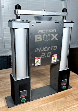
Many people don’t realize that an injection molding machine is something they can build themselves, even without a machine shop or other extensive setup. The hosts of the Canadian YouTube channel Action BOX—known to viewers as brothers Alan and Dave—described in one of their videos how they created a desktop injection molder called the INJEKTO.
Even though the YouTube channel only appeared on June 14, 2021, some of the videos have several million views. All the Action BOX content aims to show people how to do and build things, encouraging them to have ideas in the process.
Here’s an in-depth breakdown of what the Action BOX team did and why certain design decisions were made.
The Body and Frame
The design of the molds used in this manufacturing process plays a substantial role in determining whether the resulting products will function as intended. The same is true when making an injection molding machine. The design is critical for the machine’s overall functionality and performance. That’s why the Action BOX team used computer-aided design (CAD) software to flesh out the build’s specifics before making the physical version.
The creators focused on user-friendliness in the design. Two main components that make the machine work are an air compressor and a standard electrical socket, making it easy to use almost anywhere.
Much of the machine’s body consists of a 3-in. aluminum flat bar. The creators chose it because they deemed it one of the least expensive and most readily available types of raw aluminum to source. However, your decision may vary depending on your budget and how you plan to use the injection press.
The Structural Integrity
During the design process for the machine’s frame, the pair recognized that they could have welded the parts together or made them slot into each other to create support. However, simplicity was the goal, especially because they knew some people who build this product might not have machine shop access. The design includes well-placed brackets to hold everything together.
One of the brackets also serves as a shelf for the metal bar pulled down with pneumatic cylinders during the machine’s operation. The brothers decided putting the bracket there would increase tolerance to the resultant high stresses.
Engineers typically use reverse engineering to rebuild or improve upon old designs when trying to see how a product works and recreate it without blueprints. However, you don’t have to do that here because the video about making the INJEKTO shows the creators taking the machine apart and showing what’s inside.
The Injection Chamber
The team made the heated injection chamber by turning a piece of aluminum round stock on a lathe to get its cylindrical shape. They decided the second prototype would use steel instead of aluminum, making the machine more durable.
Injection molding works by pressing liquid plastic into a shaped mold. The injection chamber has a tapered top to help funnel the plastic pellets into the inlet. A second iteration of the injection chamber’s top includes a funnel extension accommodating more pellets.
Heater bands wrap around the injector chamber’s tubed shape, and a silica sleeve promotes warmth retention. The design also includes a large fan that circulates air from one vent placed on the opposite side of—and slightly above—the fan. That design decision distributes air across all the aluminum surfaces to cool them quickly.
The silica sleeve around the tube inhibits some of its heat loss but lets the component cool slightly. That gives the machine’s temperature controller more authority over the tube’s temperature since the design allows heating and cooling to occur rapidly. Otherwise, the heater bands would overheat the injection chamber’s tube, burning the plastic inside the machine and producing flawed pieces.
The Injection Tube’s Mechanism
The injection chamber’s tube also has springs on the bottom, helping the nozzle enter the mold opening with enough force to keep it mated while the injection occurs. The creators pointed out that if they design future models with larger hydraulic cylinders, they’ll probably also need to increase the spring size to maintain the desired contact.
The designers encountered a challenge while figuring out how to keep the injection chamber’s tube secure and in the right position without too much heat loss. They tackled it by using four round screws positioned around the perimeter of the chamber’s pipe, virtually eliminating surface-area contact. This approach made the pipe stable during the side-to-side operational movement, and it loses minimal heat by conduction to the frame.
READ MORE: The Basics of Rapid Injection Molding
The top of the tube mounts onto the machine with steel spacers that reduce the heat-transfer contact area. The nozzle threads into the heated tube with tapered pipe threads, preventing liquefied plastic from leaking. The creators decided against using gaskets. That makes it much easier to replace the nozzle or switch it out with a different size.
This injection molding machine also includes a precision-ground shaft that goes into the heated chamber’s long hole once the plastic pellets are sufficiently heated. It fits tight enough to move all the plastic through the machine and out the far end.
A pair of 2-in. pneumatic cylinders with a crossbar between them pulls the shaft down. The pneumatic cylinders create a 120-PSI pressure and force of more than 3,000 newtons. However, the second iteration will have 4-in. cylinders, making it more forceful.
The Air System
The machine’s front cover stays in place with four screws. The air system works when a compressor’s tube is fed into a through-wall quick connect, moving the air into an electrical solenoid. All connections to the solenoid occur via T-adapters. The team used elbow brackets to create all links to the pneumatic cylinders.
The solenoid gets 110 volts of electricity when someone turns the machine’s injection button on. The electrical flow allows air to travel through tubes snaking around to near the top of the frame. Those tubes push the air to the top of the injection cylinder.
Each of the machine’s pneumatic cylinders contains a plunger that functions like a syringe. Air forced down from the top pushes on the internal surfaces, making the whole shaft and injection ram move downward.
In contrast, releasing the pressure on the injection button pushes the air through the tubes to the cylinders’ bottoms. Then, the air presses on the bottom of the syringe plungers, raising the injection ram. The injection ram goes up once someone releases the button and serves as a safety feature if the press needs to be stopped because something’s blocking the ram.
The Electrical System
The machine’s back has a standard, three-prong power cord outlet. The main switch is directly above where the cord plugs into the back. The team ground the electrical connection to the injection molder’s all-metal frame with a yellow wire and the phase is split among four loads.
The first wire sends power to the main injection button, which connects and disconnects the phase before the current is routed back to the solenoid. The next wire goes to a junction block that causes the fan to start once someone turns on the machine. A third wire goes to the main proportional-integral-derivative (PID) temperature controller. Finally, a fourth wire connects to a solid-state relay, the machine’s main switch electronically activated by the temperature controller.
If the controller senses the temperature is not high enough, it opens the solid-state relay switch, which channels the current to the heating elements and activates them. A K-type thermocouple mounted above the nozzle measures the temperature.
However, the brothers admitted a problem with having only one thermocouple in their design. They knew it would be better to spread them throughout the build and aimed to do that with their next iteration.
Using the Injection Molding Machine
The creators begin by plugging the machine into a 110-volt power supply and giving it a couple of minutes to reach the required temperature. The display on the front of the device indicates when the temp is correct. The team used acrylonitrile butadiene styrene (ABS) plastic, so they knew the right nozzle temperature was approximately 220°C.
They plugged the air compressor into the back while waiting for the machine to get hot enough. Doing that forced the side cylinders up, putting the injection ram in the right position for pressing hot plastic into the mold.
READ MORE: Small Parts: Design for Micro-Molding Fuels Miniature Component Applications
The creators filled the injection tube with plastic, then inserted their mold. After pushing the mold upward, they placed a spacer below it to maintain contact with the nozzle. However, the creators also suggested elevating the mold on a scissor lift, provided both components are small enough to fit under the machine’s nozzle.
Next, they pressed the injection button and kept it depressed for a few seconds longer than necessary, giving the plastic time to start cooling and hardening. Waiting like that prevents the plastic from flowing back out.
The machine’s creators were also curious about how much plastic it could hold, so they filled the injection tube, extruded all the material out and placed the contents on a scale. The results showed the machine contained 27.6 grams—more than sufficient for home projects.
The molds were created on a CNC machine. However, you can also explore other options, such as using a 3D printer to make what’s needed for your project.
Making Your Injection Molding Machine
If you want to make the injection molding machine described here, you can buy the INJEKTO 2.0 kit, which features all the improvements the brothers intended to make during a second iteration. They designed it to work with 3D-printed molds, as well as those made with a CNC machine.
However, you might also decide you have enough ideas—between your knowledge and what’s covered above—to make a design that improves upon what’s here and is better suited to your needs. In any case, knowing what others have tried when building injection molding machines is always helpful.
Emily Newton is a technology and industrial journalist. She is also the editor-in-chief of Revolutionized. She has more than five years of experience covering warehousing, logistics and distribution.
About the Author

Emily Newton
Emily Newton is a technology and industrial journalist. She is also the editor in chief of Revolutionized. She has over five years covering stories about warehousing, logistics and distribution.

