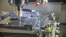
Top Tips on Designing Parts for CNC Machining
READ MORE: Using Desktop 3D Printing to Get More Out of CNC Machines
CNC might seem like magic. After all, an engineer need only design a part, send it through some CAM software, and then let the CNC machine do it’s thing and automatically cut a part. But that’s not quite right. There are limits on CNC machining engineers need to be aware of. For example, not all shapes and features an engineer can dream up can be created even with all the advances made in tooling and CNC controls.
Here is some advice on how to take advantage of CNC’s capabilities and avoid its limitations.
Tolerances
Tolerances are the acceptable range or size of a part’s dimensions. They are determined based on the part’s form, fit, and function. Engineers should keep in mind that tighter tolerances add costs due to increased scrap, additional fixturing and special measurement tools. Tight tolerances also add costs due to increased inspection times. Depending on the tolerances requested by the designer, costs can more than double compared to those for machining to standard tolerances. Tighter tolerances should only be used if they are needed to meet the part’s design criteria.
Tighter tolerances also extend CNC cycle times as the CNC machine must slow down to hold tighter tolerances.
If engineers do not add tolerances to the drawing, model, or specification sheet given to CNC vendors, they may follow their own general specifications regarding tolerances. These specifications may vary from one company to another. And some vendors companies do not have default tolerances settings and require that customers provide them.
The best way to apply tolerances is to only apply tight and geometric tolerances to critical areas, which will lower overall costs.
Size Limitations
For milling, part size is limited by the machine’s capabilities and the depth of cut required part features. Remember that build-space dimensions don’t equate to part size. For example, a Z travel of 38 in. doesn’t mean a part can be machined to that depth or height. Depending on the part’s size and features that need to be machined, the part’s Z height must be less than 38 in. to accommodate tool clearance and depth of cut. Features and part size determine the part’s machinable height.
For lathes, the part size depends on the build space and the part’s diameter and length. CNC vendors may offer a live tooling lathe. It can dramatically decrease lead times, but it also increases the number and type of features that can be machined by offering CNC milling functions within the lathe.
Material Selection
Material selection is critical in determining the overall functionality and cost of the part. Engineers must define the final part’s important material characteristics—hardness, rigidity, chemical resistance, heat treatability and thermal stability, just to name a few.
Materials that undergo CNC machining usually come in blanks, and the blank’s size limits the size of the part. For example, if the finished part will measure 3.5 × 2 × 1 in., then the material blank size would need to be a minimum of 3.75 × 2.125 × 1.125 in. tall in raw form. Material blank thickness should be considered during the design process.
READ MORE: Book Review: Hot Tech Cold Steel
A good rule to follow is use blanks at least 0.125 in. larger than the part. For example, if the final dimensions are to be 1 × 1 × 1 in., the blank should be 1.125 × 1.125 × 1.125 in. to allow for the variations in blank size. In this example, if the engineers decided the part’s form, fit, and function would not be changed if the final part dimensions were 0.875 × 0.875 × 0.875 in., then a standard 1 x 1 x 1-in. block could be used. This lowers material costs compared to starting with a larger blank.
For softer metals, such as aluminum and brass, as well as plastics, machining times are usually less compared to those for harder materials, and this saves time and money. Those harder materials, such as stainless and carbon steel, must be machined at lower spindle speeds and machine feed rates. For example, aluminum is typically machined about four times faster than carbon steel, and eight times faster than stainless steel.
The material used is a major component of a part’s final cost. For example, 6061 aluminum bar stock is approximately half the price per pound of aluminum plate, and 7075 aluminum bar stock can be two to three times the cost of 6061 bar stock. The cost for 304 stainless steel is about two to three times that of 6061 aluminum and about twice as much as 1018 carbon steel. If the design doesn’t warrant the properties of a carbon or stainless steel, consider using 6061 aluminum to minimize material expenses.
Plastics are often a less expensive alternative to metals if the design doesn’t require the rigidity of a metal. Polyethylene, for example, is easy to machine and costs about a third the price of 6061 aluminum. In general terms, ABS is about 1.5 times the cost of acetal; nylon and polycarbonate are approximately three times the cost of acetal. But tight tolerances can be harder to hold with plastics, and parts could warp after machining because of the stresses created when plastic is machined away.
Complexities
The more complex the part, which means contoured geometry or multiple faces that must be cut, the more costly it is due to additional setup time and time to cut the part. When a part can be cut in two axes, setup and machining can be done faster, thus minimizing costs.
For simple two-axis parts, more material is removed as the tool moves around the part. With more complex parts, some areas need to be cut with X, Y and Z axes moving together.
READ MORE: Top 11 Myths Of CNC Machining
To create a complex surface with a good surface finish, small cuts are preferred. It increases machining time, so the price of the part increases. To minimize costs, design using only two-axes cuts. This might not be possible if the part needs a certain look or functionality. Another cost saving approach is to keep things consistent such as internal corner radii and tapped holes. This saves time by lowering the need for tool changes.
Perhaps the best way to lower the cost of CNC machining complex parts is to use five-axis machining. Five-axis machining lets the cutting tool and part move simultaneously around up to five axes. This means toolpaths are more efficient and fewer setups are needed. Three-axis machining often calls for complex fixtures that must be custom made to hold the part in the orientation necessary to create the feature. Five-axis capable machines also let the cutting tools remain tangential to the cutting surface. So, more material can be removed with each pass of the tool, and it leaves a better surface finish.
Fillets and Undercuts
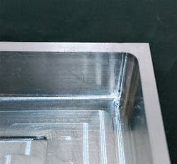
When using CNC vertical or horizontal milling machines, all interior vertical walls must have a radius. That’s because a round tool spinning at high rpms is removing the material. Designs should take into account areas where this limitation will create radii.
For inside corner radii, it may be best to use a non-standard radius because end mills need clearance to turn and continue milling when tracing internal corners. If a part has a 0.25-in. interior radius, a standard end mill would need to hammer the corner, come to a complete stop, pivot 90 deg., then resume cutting. This slows machining, which adds costs and causes vibration. But adding just 0.02 to 0.05 in. (0.508 to 1.27 mm) to the internal radii, will let the turn without coming to a complete stop. This will not only reduce cost but also improve the finished CNC parts.
In general, the larger the radius, the lower the cost. That is because a larger tool can be used and it will remove more material per cut, thus reducing the machining time. For example, a tool with a 0.125-in. diameter would take approximately 1.5 times longer than doing the job with a 0.187-in. diameter tool, and about twice as long as using a 0.250-in. tool.
Even though small-radius tools (down to a 0.015-in. radius) are available, sometimes the depth the tool needs to go into the material makes it impossible to cut a small diameter hole because the tool is not commercially available. And if the tool is custom-made, the machining costs would increase significantly because it could only make small cuts which extends manufacturing times.
If the cut depth exceeds twice the diameter of the cutting tool, the tool’s feed rate of the tool needs to be lowered, leading to increased cycle time and costs. For every doubling of the cut depth, the feed rate is more than halved, which more than doubles the time to cut the feature. The maximum cut depth-to-tool diameter ratio is six times; beyond that, special tooling must be ordered. For example, if a 0.125-in. diameter tool is used, the deepest cut depth should be 0.750 in. before having to use a custom tool.
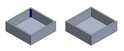
When creating a floor radius that meets a corner, it’s much easier to machine if the floor radius is smaller than the corner radius. With modern CAD systems, it is simple to make computer generate the same size floor and wall radius. However, this makes it difficult to remove material in corners. With a floor radius smaller than the vertical wall radius, the same tool can remove material and create a smooth flow through corners.
Engineers sometimes design features in areas standard machining tools cannot reach, thus creating an undercut region on the part.
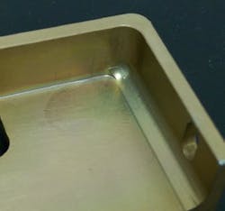
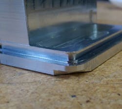
Care must be taken when designing an undercut for a couple of reasons. First, the undercut may require the creation of a special tool if the feature is not a standard dimension. In the example below, the radius in the slot is 0.053 in. A costly custom tool would be required to create the geometry, which would significantly increase the part’s cost, especially if only a few parts are to be manufactured. If a standard 0.062-in. radius is used, however, the cost of the tool would be less than half the custom tool’s cost.
The second reason to be careful when designing undercuts is to ensure the undercut is not too deep or cannot be reached. Since the required tool has a horizontal cutting blade attached to a vertical shaft, it limits its cut depth. There is no hard-and-fast rule on the depth of the undercut, but the shallower it is, the better. Also, when designing an undercut feature, only create undercuts in areas that the tool can reach.
There are several ways to create threads in parts, including cut taps, form taps and thread mills. These are all effective methods, but design engineers should keep a few things in mind:
- Always choose the largest thread size possible allowed by the design because it simplifies the manufacturing process. The smaller the tap, the greater the chance the tap will break during production.
- Only thread to the length necessary. Deep, threaded holes increase the part’s cost due to the specialized tooling that may be needed to meet the depth requirements.
- Try to use off-the-shelf thread sizes to save on costs.
About the Author
Voice Your Opinion!
To join the conversation, and become an exclusive member of Machine Design, create an account today!

Leaders relevant to this article: