Precision drive applications often call for planetary gearheads connected to servomotors with high output speeds, 3,000 to 10,000 rpm. These gearheads offer more than three times the torque and up to 30% higher speed-reduction ratios than comparable inline reducers.
All of these parameters -- high input speed, high torque, and high speed-reduction ratios -- can cause gearheads to emit unacceptable noise unless the drive designer takes appropriate counter measures. Such measures start with specifying certain gearhead design parameters, then following with an installation process that minimizes vibration sources in both the gearhead and other drive components.
Basic construction
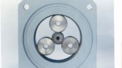
Traditional planetary gearheads consist of three or four spur gears, called planets, and a smaller central pinion, or sun, surrounded by a ring gear with teeth on the inside diameter. The ring gear is usually stationary and the planets rotate within the ring. This multipleplanet arrangement spreads the torque among several gears, increasing torque capacity per unit volume.
More advanced planetary configurations use helical gears. The teeth are cut across each gear at an angle, such that the gears gradually mesh, thereby producing less noise and vibration. This design also increases the number of teeth in contact between mating gears, which alleviates the load on each tooth, further reducing noise, vibration, and wear.
Noise factors
Using helical gears is one way to limit noise and vibration. But other factors contribute to noise as well. They include design shortcomings, manufacturing process limitations, and assembly errors. The three main causes are:
• Tooth profile deviation. • Impact between mating gears as they engage. • Changing stiffness of mating teeth during contact.
For each of these conditions, you, as drive designer, can specify certain tooth design parameters that will reduce the noise effect.
Tooth profile deviation. If mating gears had perfect involute tooth profiles, they would run very smoothly. Because of limited accuracy, however, gear making machines only approximate this perfect tooth profile.
To minimize this approximation, request precision planetary gearheads containing sun and planet gears that meet American Gear Manufacturers Association (AGMA) quality number 14 or Deutsche Industrie Norm (DIN) quality number 4. For standard industrial gears, AGMA numbers 10 to 12 (DIN numbers 6 to 8) are adequate.
Impacts between gears. When gear teeth engage, the impact between them may cause noise and wear, depending on the gear design and manufacturing methods. Severity of this impact depends on bending stiffness of the teeth as they deform under load after the tip of one tooth contacts the lower part of the mating tooth near its root (fillet radius). The impact severity can be relieved during manufacturing by grinding a small relief (about 0.00004 in.) at both tip and root areas of the tooth profile.
Additionally, gear shaft misalignment causes mating gear teeth to contact at one edge of each tooth face. This contact is usually accompanied by a noise-producing impact, and subsequent tooth deformation. Crowning the tooth face (by grinding) reduces the impact and counteracts the resultant noise and vibration.
Changing tooth stiffness. Most gear pairs have a fractional number of teeth in contact as they roll against each other, and this causes the stiffness to vary. With a contact ratio of 2.7, for example, the number of teeth in contact continually changes between two and three. When three teeth are in contact, their combined stiffness is larger and the deflection is smaller than during the contact of two teeth.
This continually changing stiffness is another source of noise and vibration. Its effect can be minimize by specifying that the gearsets have a large, whole-number contact ratio, preferably 3.0.
Further measures. These gearhead manufacturing and assembly steps will also reduce noise:
• Use a ductile cast iron GGG 60 housing, which has good damping characteristics, and reinforce the input side to rigidize it. • Machine the bearing seats in one operation to ensure accurate alignment of the gear shafts and the mating gears. • For high-speed operation (over 1,000 rpm), use balanced shafts. • Make sure the gear pairs and housing are dimensionally matched before assembling the gearhead.
Application tips
As the drive designer, you can require that the gearhead manufacturer implement any of the noise-reduction measures described earlier. However you can also apply the drive components in ways that ensure quiet, vibration-free performance. The following steps will help, especially in high-speed servo applications:
• Bolt the gearhead mounting flange to a stiff and rugged support. • Use a balanced motor (manufactured to close tolerances). • In attaching the motor and gearhead, set clamp screws with a torque wrench per manufacturer's instructions. • If the maximum speed is over 500 rpm, dynamically balance timing belt pulleys on the gearhead output shaft. • Place belt pulleys as close as possible to the gearhead on its output shaft so the radial overhung load is minimal and does not exceed the permissible value for the gearhead. • When mounting any device on the gearhead output shaft, don't strike it with a hammer because this can damage the shaft and bearings. • If the planetary unit drives a rack and pinion system, make sure they are properly aligned and that the center distance of rack and pinion are accurately set according to the rack manufacturer's directions. Otherwise, gear tooth chatter may result. • Select a control and resolver with comparable accuracy. A mismatch can cause rough acceleration that leads to gearhead rattling. • Make sure the control has a fine tuning adjustment to minimize overshooting after accelerating to a desired speed. Overshooting also leads to gearhead rattling. •Select a gearhead such that the ratio of gearhead and motor inertia to machine inertia is low, preferrably 1:1. If the ratio exceeds 1:4, the large machine inertia can also lead to rough acceleration and rattling.
Bernd Stober is president of Stober Drives Inc., Maysville, Ky.


